
Universal motor with a device for removing dust

a technology of dust protection and universal motor, which is applied in the direction of dynamo-electric machines, rotary current collectors, electrical apparatus, etc., can solve the problems of additional manufacturing costs and the inability of dust protection devices to remove large amounts of material particles from the commutation region,

Inactive Publication Date: 2008-01-03
HILTI AG
View PDF6 Cites 8 Cited by
  • Summary
  • Abstract
  • Description
  • Claims
  • Application Information

AI Technical Summary

Benefits of technology

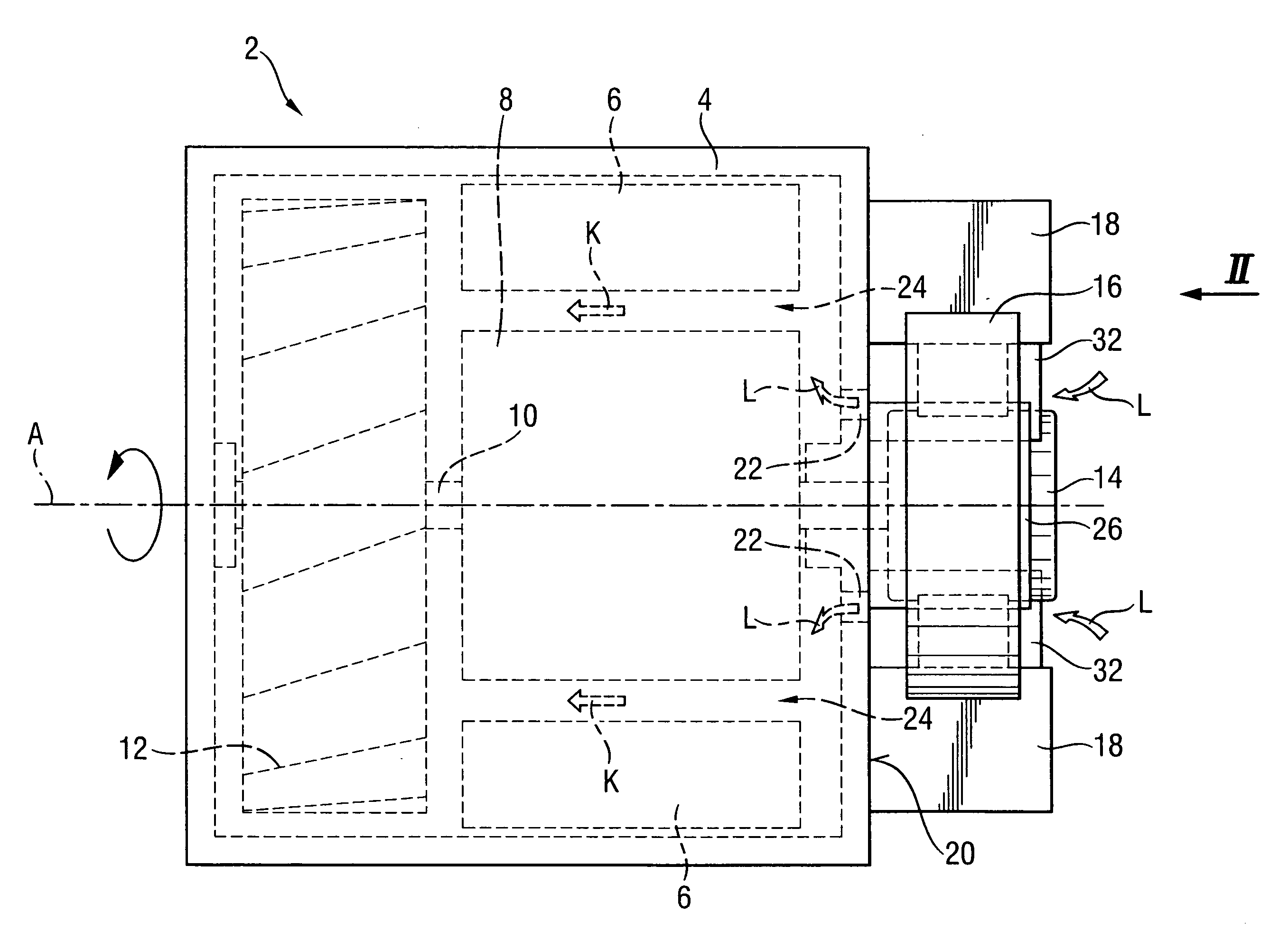
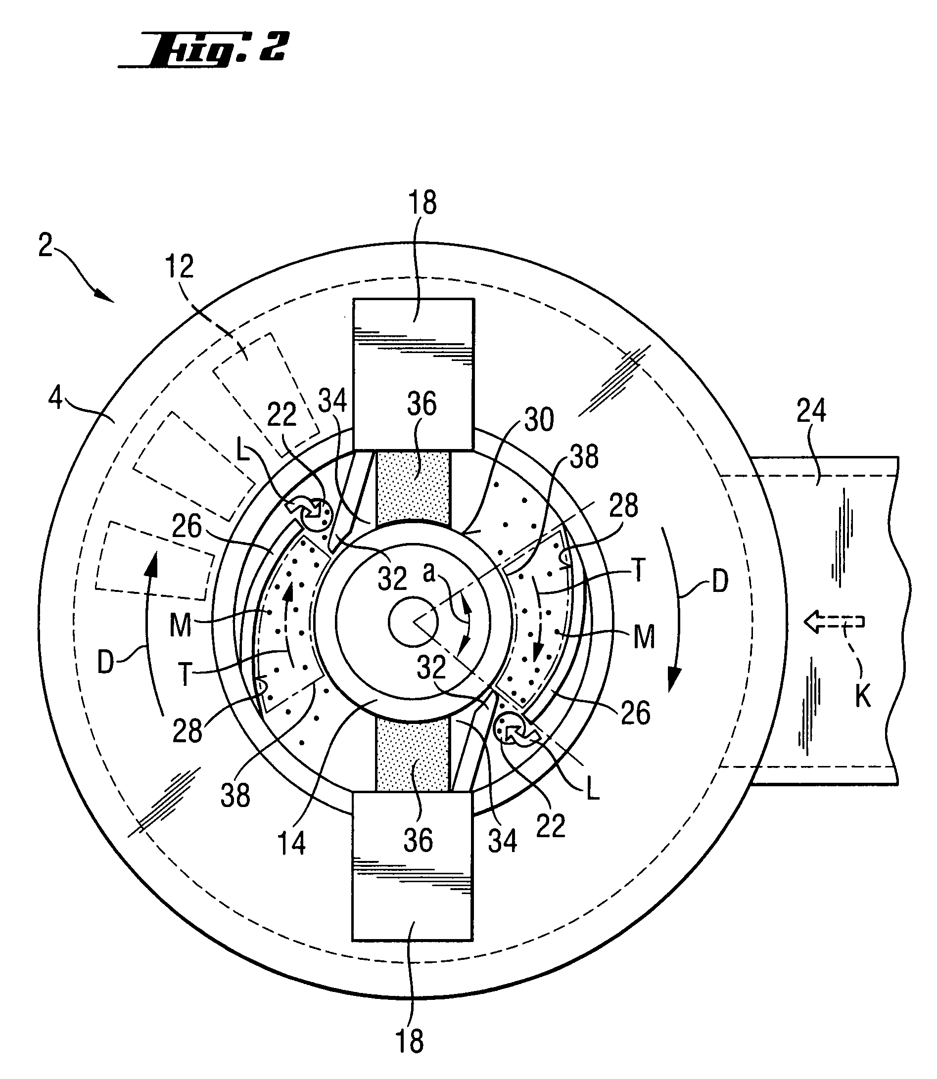
[0009] This and other objects of the present invention, which will become apparent hereinafter, are achieved by providing a universal motor in which the guide member has a smooth concave guide surface located between the two carbon brushes and extending adjacent to an outer surface of the commutator and toward a suction opening connected with the cooling flow path. The guide surface is mathematically smooth, i.e., is without any steps, and extends adjacent to the commutator outer surface in the radial direction. With such guide surface, during operation, the circumferential speed of the commutator accelerates an air layer between the commutator outer surface and the guide surface in the tangential direction, i.e., in the circumferential direction. The material particles, which are carried by this air layer, are pressed against the guide surface due to their inertia in accordance with a cyclone effect, and are displaced along the guide surface in a direction toward the suction opening. In this way, with a simple and economically produced guide member, a better removal of material particles is achieved. Thereby, there is provided a universal motor the service life of which is increased even when the motor is used in a hand-held power tool and operates in a heavily dust-laden environment.
[0011] According to a particularly advantageous embodiment of the present invention, the distance between the guide surface and the outer surface of the commutator diminishes in a direction of the suction opening. Thereby, a certain nozzle effect is achieved. The nozzle effect increases the speed of the air layer between the guide surface and the commutator as the air layer is displaced toward the suction opening, which also increase segregation.
[0012] Advantageously, a transversely extending baffle member is provided on a side of the suction opening remote, in the circumferential direction, from the guide member. The baffle member insures a reliable entry of the material particles, which are carried by the air layer, in the suction opening.
[0013] Advantageously, the baffle member is arranged on a side of the brush guide adjacent to the suction opening. Thereby, a respective carbon brush can be reliably shielded from material particles carried by the air layer adjacent to the outer surface of the commutator.
[0016] In a particularly advantageous embodiment of the invention, the baffle member, the guide member, and the suction opening are provided on the brush holder. This insures an easy mounting of the dust protection means, together with the brush holder.
[0017] It is advantageous when each of the carbon brushes, has on both sides in a circumferential direction, respectively, a baffle member, a guide member and a suction opening. This insures a dust protection of a universal motor rotatable in opposite directions.

Problems solved by technology

The drawback of the known universal motor consists in that the guide members, which are formed by hood members, have a relatively complex construction, which involves additional manufacturing costs.
In addition, the provided dust protection means is not suitable for removing large amounts of material particles from the commutation region, which are produced when, e.g., hand-held power tools, in particular drills or chisel tools are used.
This is because of high flow losses within the guide members and a rapid dust deposition.

Method used


Image

  • Universal motor with a device for removing dust
  • Universal motor with a device for removing dust
  • Universal motor with a device for removing dust

Examples


Embodiment Construction

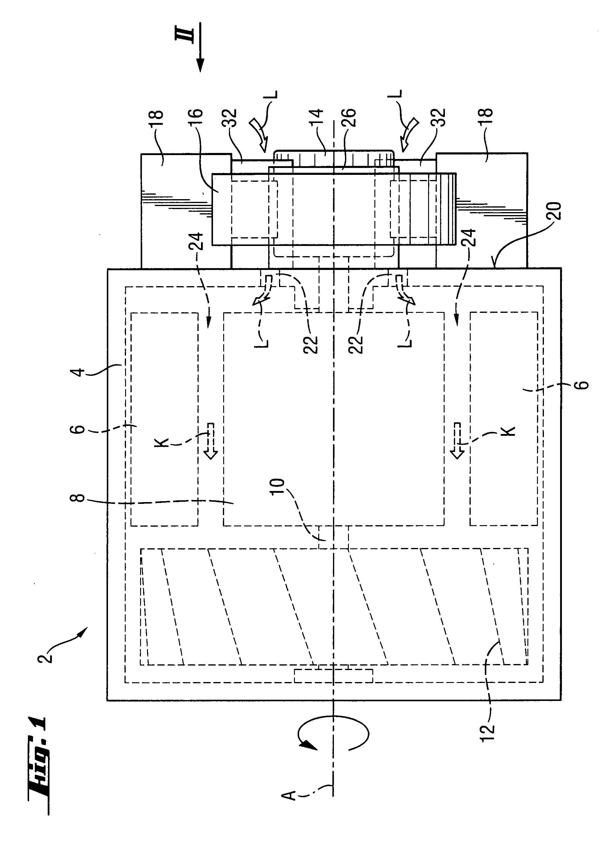
[0022] A universal motor 2 according to the present invention, which is shown in FIG. 1, is designed for use in a electrically operated hand-held power tool such as, e.g., drill or chisel power tool. The universal motor 2 has a housing 4 in which a stator 6, a rotor 8, and a ventilation device 12, which is mounted on the motor shaft 10, are located. On an end of the motor shaft 10 remote from the ventilation device 12 and extending outside of the motor housing 4, a commutator 14 is arranged. Around the commutator 14, an annular brush holder 16, which supports two brush guides 18, is provided.

[0023] In a wall 20 of the motor housing 4 adjacent to the commutator 14, there are provided two suction openings 22. When during an operation of the universal motor 2, the ventilation device 12 is rotated about a motor axis A in order to generate a cooling flow K along a cooling flow path 24, air from the commutator 14 enters in the motor housing 4 through the suction openings 22, as shown wit...


PUM


Abstract

A universal motor (2) includes at least two carbon brushes (36) contacting the commutator (14), a ventilation device (12) for producing a cooling flow (K), and a dust protection arrangement for preventing penetration of material particles (M) into the commutation region (34) and including at least one guide member (26) that provides for delivering of the material particles (M) in the cooling flow (K), with the at least one guide member (26) having a smooth concave guide surface (28) located between the two carbon brushes (36) and extending adjacent to an outer surface (30) of the commutator (14) and toward a suction opening (22) connected with the cooling flow path (24).

Description

BACKGROUND OF THE INVENTION [0001] 1. Field of the Invention [0002] The present invention relates to a universal motor having a commutator, at least two carbon brushes electrically contacting the commutator in respective commutation regions, a ventilation device for producing a cooling flow in a cooling flow path, and dust protection means for preventing penetration of material particles such as dust and the like, in particular, produced during operation of a hand-held power tool, into the commutation region and including at least one guide member that provides for delivering of the material particles in the cooling flow. [0003] 2. Description of the Prior Art [0004] In universal motors of the type discussed above, the commutation regions are protected by the dust protection means from the erosion action of the material particles, which increases the service life of the motors. [0005] U.S. Pat. No. 6,097,128 discloses a universal motor with two carbon brushes held in respective brus...

Claims


Application Information

Patent Timeline
Patent Type & Authority Applications(United States)
IPC IPC(8): H02K9/00H02K23/64H01R39/38
CPCH01R39/48H02K13/10H02K9/06H02K5/148
Inventor BRAML, GEORGFRITSCH, FRANKBURGER, HELMUTOHLENDORF, OLIVER
Owner HILTI AG
Learn More