
Panel fastening method and panel member for automobile

a technology for automobiles and fastening methods, applied in the direction of roofs, manufacturing tools, transportation and packaging, etc., can solve the problems of increasing reducing the efficiency of the process, and generating shunt currents. , to achieve the effect of reducing the number of fabricating steps and high fastening strength

Active Publication Date: 2007-12-27
HONDA MOTOR CO LTD
View PDF10 Cites 17 Cited by
  • Summary
  • Abstract
  • Description
  • Claims
  • Application Information

AI Technical Summary

Benefits of technology

[0017] One or more embodiments of the present invention provide a panel member for an automobile providing a hem portion excellent in an outlook, having a high fastening strength and capable of reducing a number of fabricating steps in a panel member for an automobile requesting a three-dimensional shape having a number of radii of curvature at a hem portion.
[0018] In addition, one or more embodiments of the present invention provide a panel fastening method capable of promoting general purpose performance and capable of fabricating a panel including a hem portion having a sufficient bonding strength and excellent in an outlook and a panel structure applied with the panel fastening method.

Problems solved by technology

Therefore, there are needed a step of coating an adhering agent, a step of carrying out spot welding and a step of coating the seal member 104 and the like to pose a problem that a number of fabricating steps is increased.
Furthermore, the portion of folding to bend the outer panel 100 is operated with a force in an arrow mark B direction in FIG. 25 (a direction widening from RO portion), the folded-to-bend portion is slightly rounded, so-to-speak sagging is brought about by increasing a radius of curvature RO and therefore, there poses a problem that the outlook is further deteriorated.
Meanwhile, according to the background art constitution, welding is carried out only from an upper side of FIG. 28, that is, the side of the hem flange portion 300b (indirect welding) and therefore, a bonding portion cannot be pressed sufficiently, further, a shunt current is liable to be generated and therefore, it is difficult to achieve a sufficient bonding strength.
Further, a facility of a C gun type used in an ordinary spot welding apparatus or the like cannot be used to divert, further, also the back bar 306 matched to the shape of the work is also needed and therefore, there poses a problem that it is difficult to widely use the facility.

Method used


Image

  • Panel fastening method and panel member for automobile
  • Panel fastening method and panel member for automobile
  • Panel fastening method and panel member for automobile

Examples


Embodiment Construction

[0072] Exemplary embodiments of the invention will be described with reference to the accompanying drawings.

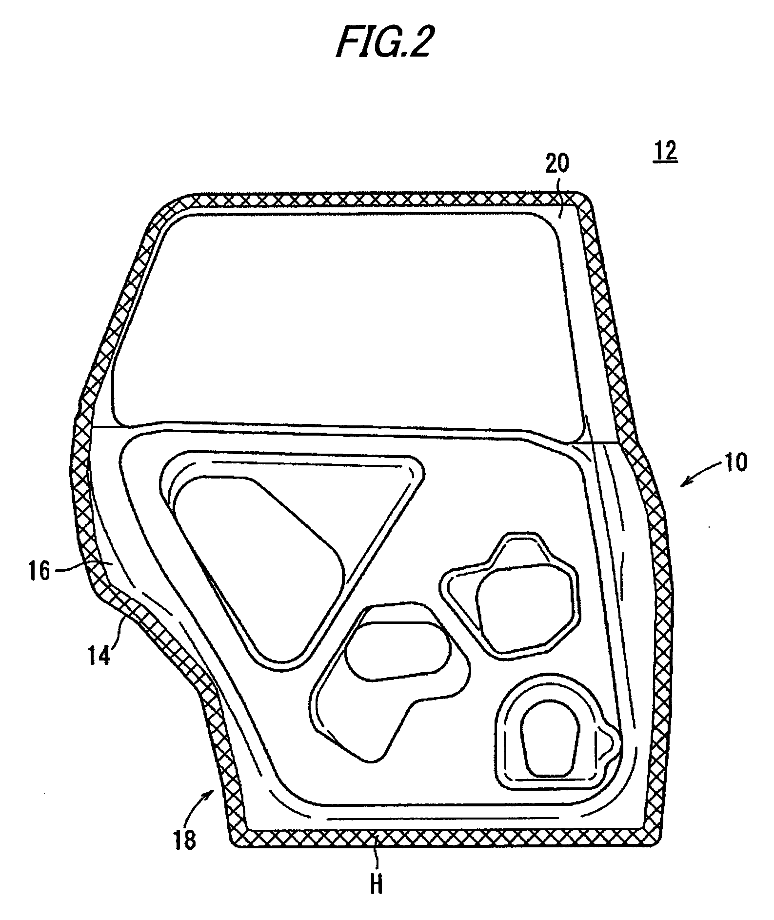
[0073]FIG. 1 is a partial perspective view of an automobile rear door 12 constituting an example of applying a panel member 10 for an automobile according to a first exemplary embodiment of the invention. FIG. 2 is a front view of the automobile rear door 12 viewed from an A arrow mark direction in FIG. 1 (a direction of viewing the automobile rear door 12 from a vehicle inner side).

[0074] The automobile rear door 12 is constituted by the panel member 10 and a window frame 20 attached to an upper portion of the panel member 10. The panel member 10 is formed by fastening an outer panel 14 and an inner panel 16 constituting plate members by roll-fastening at a hem portion 18. The outer panel 14 and the inner panel 16 are formed, for example, by sheet metal materials (made of metal) punched in predetermined shapes.

[0075] The hem portion 18 formed by being roll-fastened as desc...


PUM

PropertyMeasurementUnit
angleaaaaaaaaaa
radius of curvatureaaaaaaaaaa
thicknessaaaaaaaaaa

Abstract

A panel member 10 for an automobile includes a hem portion 18 roll-fastened in a state of overlapping an outer panel 14 and an inner panel 16. At the hem portion 18 of the panel member 10, the outer panel 14 and the inner panel 16 are roll-fastened in a state that a front end face 14a of the outer panel 14 and a front end face 16a of the inner panel 16 are respectively rolled-in by the inner panel 16 and the outer panel 14.

Description

[0001] This application claims foreign priority from Japanese Patent Application No. 2006-025686 (filed on Feb. 2, 2006) and No. 2006-083263 (filed on Mar. 24, 2006), the entire contents of which are hereby incorporated by reference. BACKGROUND OF THE INVENTION [0002] 1. Field of the Invention [0003] The present invention relates to a panel member for an automobile, particularly relates to a panel member for an automobile preferably used in an automatic two-wheel vehicle or an automatic four-wheel vehicle. [0004] In addition, the present invention relates to a panel fastening method for roll-fastening a plurality of panels and a panel structure applied with the panel fastening method. [0005] 2. Related Art [0006] In a background art, there is used a hemming structure of overlapping an outer panel and an inner panel and folding to bend a flange formed to erect at a hem portion of the outer panel to pinch in the inner panel at a hem portion of a panel member for an automobile of a bon...

Claims


Application Information

Patent Timeline
Patent Type & Authority Applications(United States)
IPC IPC(8): B60R13/00B21D19/08
CPCB21D19/12Y10T428/12271Y10T428/12354B21D39/021
Inventor TAO, SENOKUNAKA, KEISHIKODA, HIROTATSUAGO, SHINJI
Owner HONDA MOTOR CO LTD
Learn More