
Windshield Heat and Clean

a wiper fluid heating and windshield technology, applied in the field of windshield wiper fluid heating system, can solve the problems of significant safety and liability issues, ineffectiveness, and serious impair the field of vision of drivers, and achieve the effect of facilitating the operation of the window cleaning system

Active Publication Date: 2007-12-27
MCNAUGHTON
View PDF27 Cites 25 Cited by
  • Summary
  • Abstract
  • Description
  • Claims
  • Application Information

AI Technical Summary

Benefits of technology

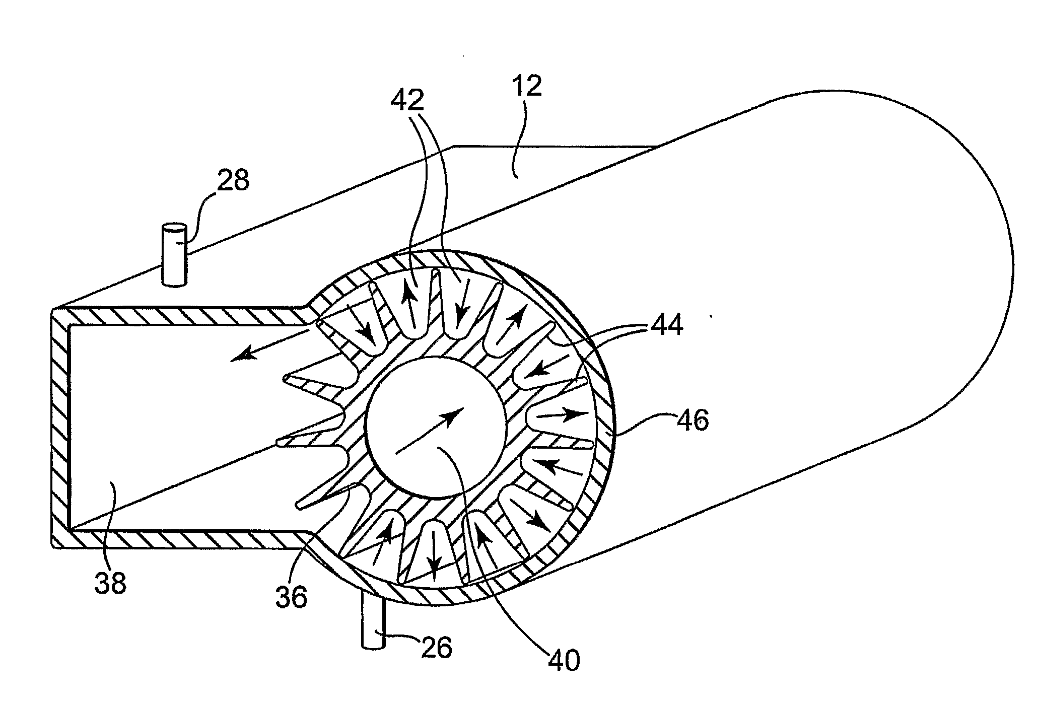
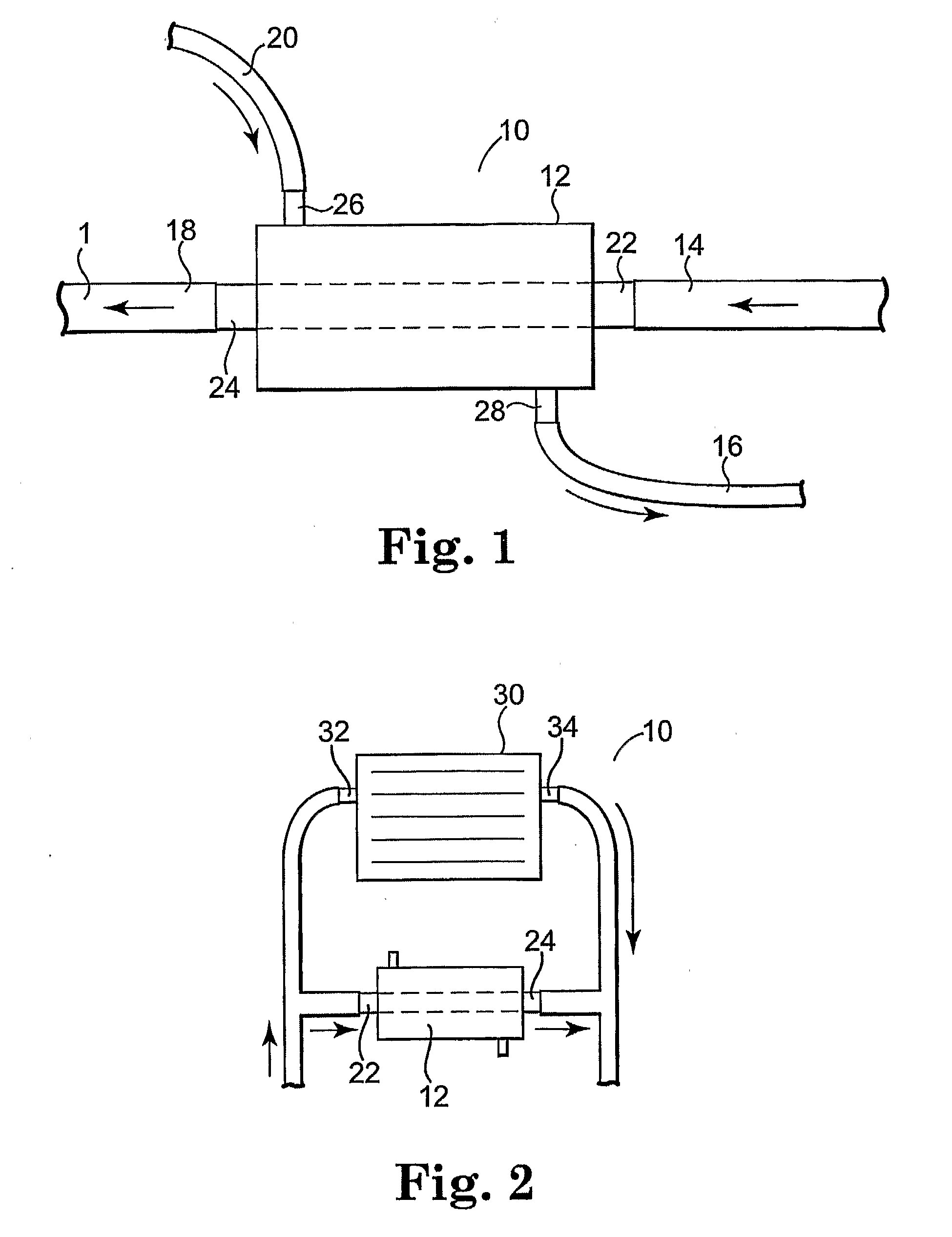
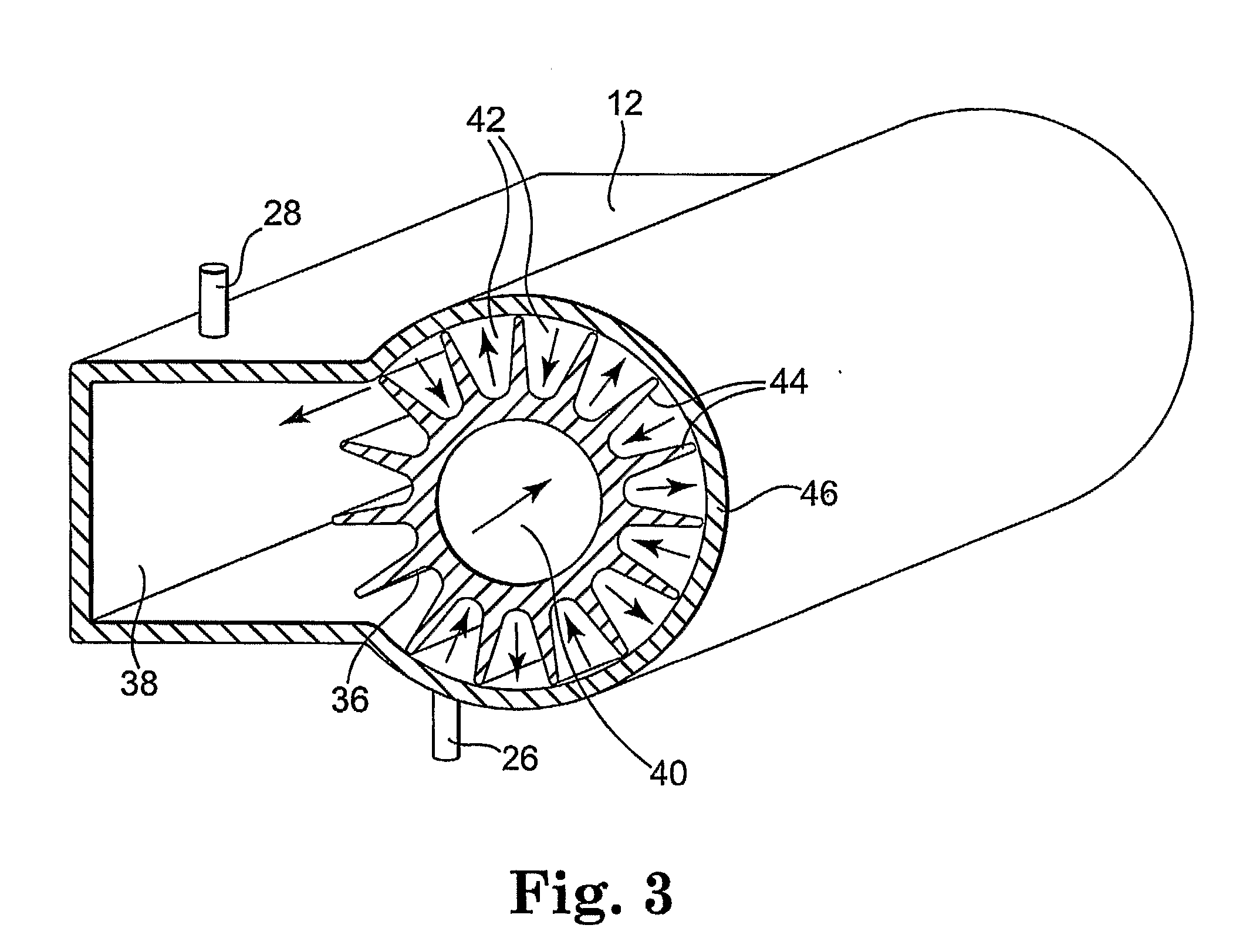
[0006] The present invention discloses a washer fluid heater system that harnesses energy lost in the form of heat from the vehicle's engine. The washer fluid heater system utilizes a heat exchanger that is installed into the engine's coolant system, either in the heat core circuit or a circuit otherwise connected to the coolant system. The heat exchanger operates without the need for electricity. The temperature of the washer fluid is increased by the passage of hot engine coolant fluid through heat exchange elements, and is thus related to the temperature of coolant flowing through the vehicle's engine. Generally, the normal operating temperature of the engine coolant is between about 150° and 220° F. Installation of the washer fluid heater system does not require modification to the vehicle, and is activated automatically when the vehicle's driver engages the factory installed windshield wiper system. Since the heat exchanger can increase the temperature of washer fluid to temperatures close to those of the hot engine coolant, the washer fluid heating system can melt snow, ice, and frozen matter on the vehicle window and wipers, and can also help dissolve and remove difficult window debris such as road grime and insects. Further, some embodiments of the washer fluid heater system release vapor onto the vehicle window or the washer fluid reservoir in order to preheat these areas and further facilitate operation of the window cleaning system.
[0007] It is considerably less expensive than other systems on the market, can be installed quickly using only hand tools, and does not compromise the integrity of the vehicle's electric system. For example, as it does not draw off battery power, it does not have the chance of creating a dead battery if the system is misused or malfunctions. The invention can be readily disassembled and cleaned for maintenance. Finally, particular embodiments of the invention are also readily adaptable to provide varying levels of performance depending on the environment in which the vehicle is typically used.

Problems solved by technology

If not cleaned, dirty windshields in motorized vehicles can seriously impair a driver's field of vision.
Effective windshield wipers are particularly important in the trucking industry, where large vehicles with heavy loads are operated for extensive periods, creating significant safety and liability issues.
While conventional windshield wiper systems operate effectively under normal conditions, they can become ineffective when confronted with either cold ambient temperatures that cause the wiper fluid to freeze on the vehicle window, or particularly troublesome material such as impacted insects or road grime that are difficult to remove.
Application of wiper fluid to a cold windshield can be particularly disastrous, as the sudden formation of a layer of frozen fluid on the windshield can render the windshield completely opaque.
This, however, is a relatively inefficient and slow way of heating the windshield.
These systems, and others found in the art, are generally expensive, cumbersome to install, and may require drilling and modifications to the vehicle chassis.
Furthermore, they require electrical current, generally from the vehicle's battery, which may decrease the life expectancy of the vehicle's battery and may result in the battery not having sufficient energy to start the car under cold conditions.
Use of electrical current is also inefficient, and there is often a significant delay from the time the unit is activated to the point where hot fluid is actually generated.
The hot fluid volume generated by these procedures is minimal, and there may be an additional warming delay between each activation.

Method used


Image

  • Windshield Heat and Clean
  • Windshield Heat and Clean
  • Windshield Heat and Clean

Examples


Embodiment Construction

[0031] The following discussion is presented to enable a person skilled in the art to make and use the present teachings. Various modifications to the illustrated embodiments will be readily apparent to those skilled in the art, and the generic principles herein may be applied to other embodiments and applications without departing from the present teachings as defined by the appended claims. Thus, the present teachings are not intended to be limited to the embodiments shown, but are to be accorded the widest scope consistent with the principles and features disclosed herein. The following detailed description is to be read with reference to the figures, in which like elements in different figures have like reference numerals. The figures, which are not necessarily to scale, depict selected embodiments and are not intended to limit the scope of the present teachings. Skilled artisans will recognize the examples provided herein have many useful alternatives fall within the scope of t...


PUM


Abstract

A washer fluid heater apparatus in embodiments of the invention may include one or more of the following features: (a) a heat exchanger having a washer fluid inlet to allow washer fluid to enter the heat exchanger and a washer fluid outlet to allow the washer fluid to exit the heat exchanger; and (b) a coolant passage traversing through the heat exchanger having a coolant inlet and a coolant outlet, the coolant inlet and coolant outlet operably coupled to an engine's coolant system to allow passage of engine coolant through the heat exchanger.

Description

FIELD OF THE INVENTION [0001] The present invention relates to a heating system for vehicle windshield wipers, and more specifically to a windshield wiper fluid heating system utilizing engine heat to heat the windshield wiper fluid. BACKGROUND OF THE INVENTION [0002] Windshield wipers are a standard feature on the majority of motor vehicles in use today, and are used to clear vehicle windows of various types of dirt and debris. For windshield wipers to function properly, they must be supplied with a jet of windshield wiper fluid that helps to dissolve the dirt and debris and carry the material off of the window, assisted by the motion of the windshield wipers. If not cleaned, dirty windshields in motorized vehicles can seriously impair a driver's field of vision. Effective windshield wipers are particularly important in the trucking industry, where large vehicles with heavy loads are operated for extensive periods, creating significant safety and liability issues. [0003] While conv...

Claims


Application Information

Patent Timeline
IPC IPC(8): B60H1/02B60S1/48F28D7/10F28D9/00
CPCB60S1/487F28D9/0031F28D7/106F28F2250/102Y10T137/87362
Inventor MCNAUGHTON, PATRICK JAMES
Owner MCNAUGHTON
Learn More