
Panel filter with frame

a panel filter and frame technology, applied in the field of panel air filters, can solve the problems of affecting the shape and structural strength of the finished frame, extra manufacturing cost or inefficiency, and the complexity of the prior design is also more than necessary

Active Publication Date: 2007-12-27
PARKER HANNIFIN CORP
View PDF28 Cites 49 Cited by
  • Summary
  • Abstract
  • Description
  • Claims
  • Application Information

AI Technical Summary

Benefits of technology

[0007]The present invention is directed toward a simplified panel filter frame that includes an interlocking feature that keeps the frame assembled during manufacture and that is particularly applicable but not limited to one-piece die cut frames and self supporting media applications. The interlock feature may be provided at the respective overlapping portions of adjacent terminating end flaps and can take a variety of different forms as indicated but not limited to the examples herein. Unlike several examples of the prior art, the invention may be accomplished with minimal modification and with little or no additional frame material necessary. Another subsidiary feature of the present invention is directed toward one or more slits in one or more of the flaps as forming the corner interlock feature. The slit can be ready struck into the terminating flaps with minimal die changes and with removing little or no paperboard material such that the slit edges may even contact each other in the unassembled state. The slit can receive the edge of an adjacent flap during assembly to hold the flaps together while the adhesive between overlapping portions of flaps is curing.

Problems solved by technology

Unfortunately, during manufacturing while the adhesive is curing, the folded panels of the frame tend to relax which can affect the shape and structural strength of the finished frame.
While there are attempts to interlock the folded panels of the frame, these attempts have complexities, result in extra manufacturing cost or inefficiency, and / or are not applicable to one piece die cut frames.
Such prior designs are also more complex than necessary and unnecessarily use more material than is required to prevent the folded panels from shifting while the adhesive cures.
However, the '587 patent requires a complex shape that uses numerous unnecessary panels, which increases the amount of material required for the blank of paperboard and the amount of time for assembling the frame member.
This configuration further uses increased amount of material and makes the design complex.

Method used


Image

  • Panel filter with frame
  • Panel filter with frame
  • Panel filter with frame

Examples


Embodiment Construction

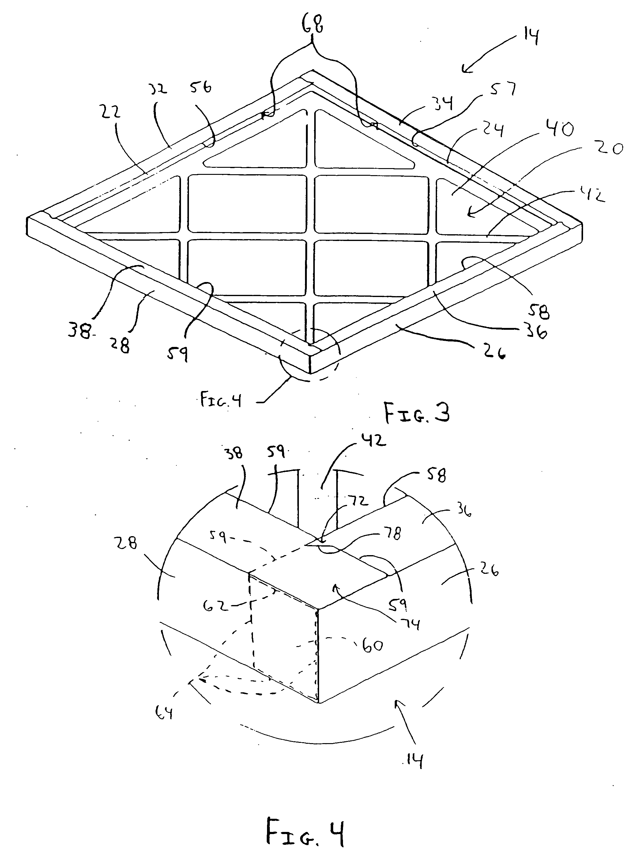
[0031]Turning now to the figures, FIG. 1 illustrates an exemplary embodiment of a one-piece die-cut blank 10 that when operably folded forms a panel filter frame 14 (see FIG. 3) for supporting a similarly shaped piece of pleated filter media 12 (see FIGS. 17 and 18). The die-cut blank 10 of FIG. 1 generally includes a substantially rectangular grill portion 20, four sidewall portions 22, 24, 26, 28 and four flap portions 32, 34, 36, 38, all integrally formed from a unitary sheet of material. Prior to folding the die-cut blank 10 to form the frame 14, the die-cut blank 10 is substantially planer and can be manufactured from paperboard, card board, corrugated board, kraft, thin plastic sheet and the like. It is preferable, but not required, that the material is a multi-ply material having at least one layer that provides an aesthetically pleasing visual appearance and feel and that can be printed with trademarks, advertising and product information. Paperboard is often typical and pre...


PUM

PropertyMeasurementUnit
angleaaaaaaaaaa
angleaaaaaaaaaa
angleaaaaaaaaaa

Abstract

A panel filter frame and panel filter are provided. The panel filter frame is made from a one-piece die-cut blank of material. The die-cut blank includes a grill portion, four sidewall portions and four flap portions all integrally connected. Individual sidewall portions are interposed between a side of the grill portion and one of the four flap portions. The plurality of portions of the die-cut blank are interconnected at fold lines. The frame is formed when the die-cut blank is folded about the fold lines and the portions are secured in the folded position by at least a plurality of interlock receptacles formed in the terminating folded portion of the die-cut blank.

Description

FIELD OF THE INVENTION[0001]This invention generally relates to air filters, and more particularly to panel air filters.BACKGROUND OF THE INVENTION[0002]Panel air filters are generally used for filtering air in forced air systems such as furnaces and ventilation systems. Panel air filters generally comprise a panel of filter media surrounded and supported by a paperboard frame. One common type of filter media used in panel filters is pleated filter media that includes a plurality of peaks and valleys. In most prior art implementations, pleated filter media have used a semi-rigid support structure other than the frame to maintain the shape of the peaks and valleys and prevent the pleats from collapsing or becoming misshapen. For example, triangular shaped wedges interposed between the pleats have been used. Alternatively, the support structure might include a wire mesh often referred to as a scrim that is copleated with the pleats and has memory that retains its shape and increase th...

Claims


Application Information

Patent Timeline
Patent Type & Authority Applications(United States)
IPC IPC(8): B01D46/00
CPCB01D46/0002Y10S55/31B01D46/521B01D46/0016
Inventor MILLER, DAVIDREYNOLDS, MITCH
Owner PARKER HANNIFIN CORP
Learn More