Transmitter Apparatus and Wireless Communication Apparatus
a technology of transmitter apparatus and wireless communication, which is applied in the direction of power management, phase-modulated carrier system, baseband system details, etc., can solve the problems of small power efficiency, insufficient transmission output level range of communication apparatus, and inability to achieve the necessary transmission output level range. achieve the effect of wide output control and high efficiency
- Summary
- Abstract
- Description
- Claims
- Application Information
AI Technical Summary
Benefits of technology
Problems solved by technology
Method used
Image
Examples
first embodiment
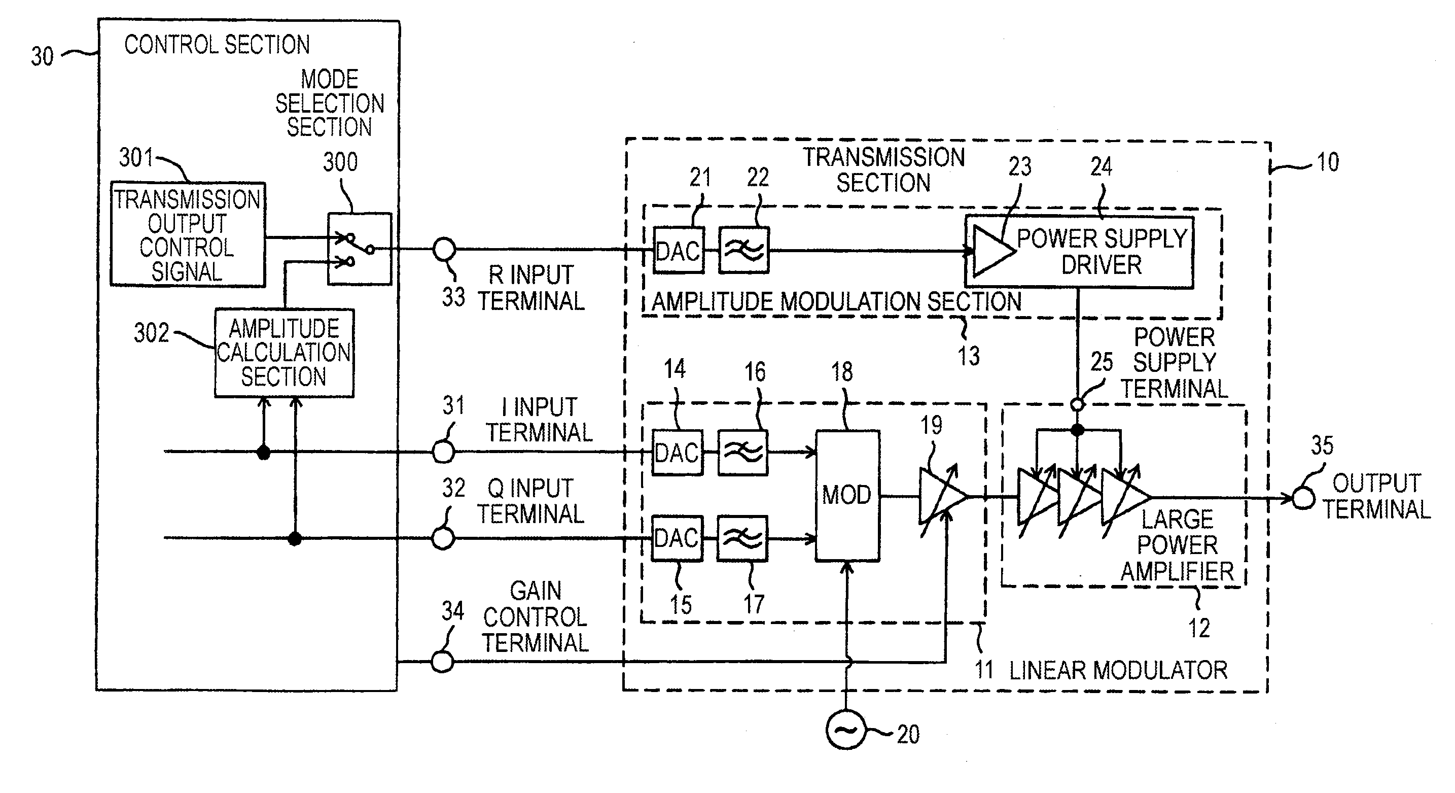
[0048]FIG. 1 is a block diagram to show the configuration of a transmitter according to a first embodiment of the invention. A transmission section 10 implementing the transmitter of the first embodiment includes a linear modulator 11, a large power amplifier 12 for performing power amplification of a transmission signal output from the linear modulator 11, and an amplitude modulation section 13 for generating power supplied to the large power amplifier 12.
[0049] The linear modulator 11 includes fixed clock input DA converters (DACs) 14 and 15 for executing digital-analog conversion according to an operation clock of a fixed frequency, low-pass filters (LPFs) 16 and 17, a quadrature modulator (MOD) 18 for executing quadrature modulation of outputs of the low-pass filters 16 and 17 at the output frequency of a local oscillator 20 and executing frequency conversion to an RF band, and a medium power amplifier 19 for amplifying output of the quadrature modulator 18.
[0050] The amplitud...
second embodiment
[0070]FIG. 5 is a block diagram to show the configuration of a transmitter according to a second embodiment of the invention. A transmission section 40 of the second embodiment differs from the transmission section of the first embodiment in part of the configuration; the configuration of the amplitude modulation section is changed, a clock switch terminal 36 is provided, and it is made possible to control operation current by changing an operation clock of a DA converter.
[0071] An amplitude modulation section 41 includes a variable clock input DA converter (DAC) 42 that can change the operation clock according to a switch signal from the clock switch terminal 36 in a transmission output control signal input section. Other components are similar to those of the first embodiment and similar components are denoted by the same reference numerals and will not be discussed again.
[0072] The variable clock input DA converter 42, which has an operation clock switch function, can change th...
third embodiment
[0075]FIG. 6 is a block diagram to show the configuration of a transmitter according to a third embodiment of the invention. A transmission section 50 of the third embodiment differs from the transmission section of the second embodiment in part of the configuration; the configuration of the amplitude modulation section is changed, a current switch terminal 37 is provided, and it is made possible to control operation current of a high-speed operational amplifier of a power supply driver.
[0076] An amplitude modulation section 51 has a power supply driver 53 including a high-speed operational amplifier (OPAMP) 52 that can change the operation current according to a switch signal from the current switch terminal 37 in an input section. Other components are similar to those of the first and second embodiments and similar components are denoted by the same reference numerals and will not be discussed again.
[0077] The high-speed operational amplifier 52, which has an operation current s...
PUM
 Abstract
Description
Claims
Application Information
 - R&D
- Intellectual Property
- Life Sciences
- Materials
- Tech Scout
- Unparalleled Data Quality
- Higher Quality Content
- 60% Fewer Hallucinations
Browse by: Latest US Patents, China's latest patents, Technical Efficacy Thesaurus, Application Domain, Technology Topic, Popular Technical Reports.
© 2025 PatSnap. All rights reserved.Legal|Privacy policy|Modern Slavery Act Transparency Statement|Sitemap|About US| Contact US: help@patsnap.com


