
Inverted Passive Optical Network/inverted Passive Electrical Network (iPON/iPEN) Based Data Fusion and Synchronization System

Inactive Publication Date: 2007-12-20
3 PHOENIX
View PDF7 Cites 66 Cited by
  • Summary
  • Abstract
  • Description
  • Claims
  • Application Information

AI Technical Summary

Benefits of technology

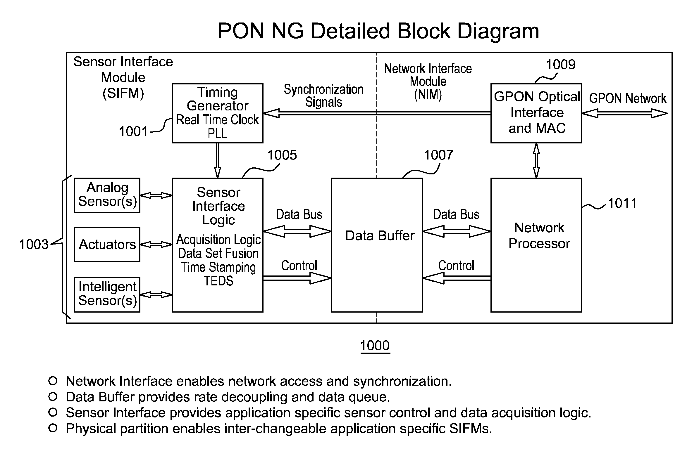
[0006] The present invention is an apparatus, method and system for time synchronizing data from various sensor types that enables data fusion and transport. To provide this capability, the present invention utilizes an inverted Passive Optical Network (PON) approach for synchronous communication. Further, the present invention introduces an inverted Passive Electrical Network (iPEN) that extends the iPON approach. Data that are in a common format with embedded time synchronization information can easily be integrated or fused and transported over such communication links. The present invention provides the ability to merge and aggregate data from a wide range of disparate sensors and systems while maintaining close synchronization. The present invention is appropriate for synchronization of data, voice, and video onto a single network and can also handle signal processing and control technologies at line rates well into the Gigabits per second (Gbps) range.
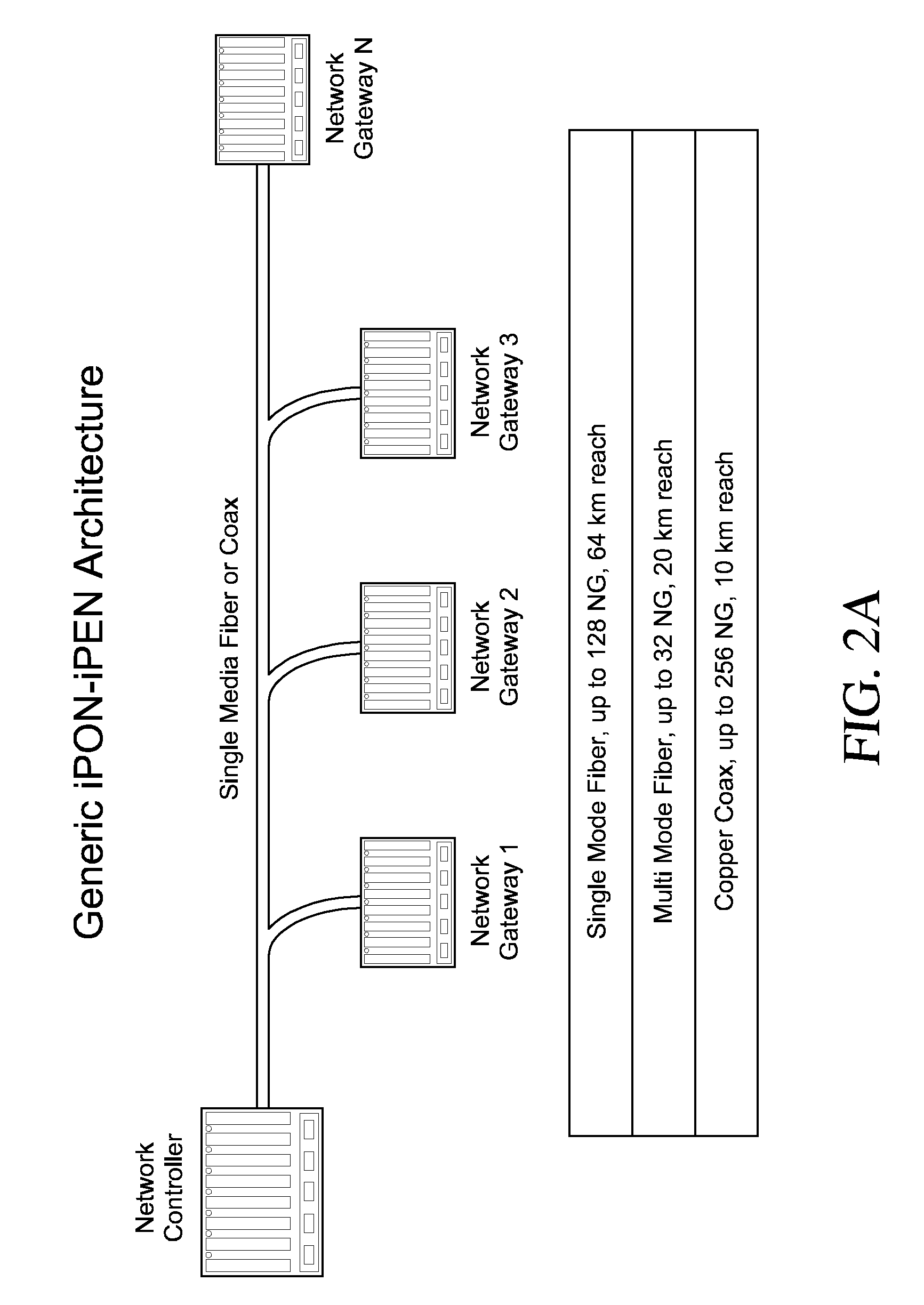
[0016] The present invention provides an approach that maintains the simplicity and industry leading availability of the legacy systems. The approach taken by the present invention is directed toward the elimination of single point failures through a simple, passive, add-drop tap implementation that minimizes the number of wires and components required to construct the data acquisition and communication network. The iPON and iPEN technologies will be described in more detail in the following paragraphs.

Problems solved by technology

The background art has not addressed such data fusion systems with both a passive and synchronous approach.

Method used


Image

  • Inverted Passive Optical Network/inverted Passive Electrical Network (iPON/iPEN) Based Data Fusion and Synchronization System
  • Inverted Passive Optical Network/inverted Passive Electrical Network (iPON/iPEN) Based Data Fusion and Synchronization System
  • Inverted Passive Optical Network/inverted Passive Electrical Network (iPON/iPEN) Based Data Fusion and Synchronization System

Examples


Embodiment Construction

[0043] The Passive Optical Network (PON) is a protocol standard (e.g., ITU-T G.983, G.984 and IEEE 802.3ah and EFM) that supports nominal line rates of 1244.160 Mbit / s and 2488.320 Mbit / s in the downstream direction and 155.520 Mbit / s, 622.080 Mbit / s, 1244.160 Mbit / s and 2488.320 Mbit / s in the upstream direction. Both symmetrical and asymmetrical PON systems have been defined and deployed. PON utilizes passive optical technology which greatly reduces the cost and power requirements while significantly enhancing system reliability.

[0044] The uses of passive optical splitters and wave division multiplexing (WDM) technologies for an individual sensor or groups of sensors is the enabling technology for highly deterministic coherent sampling between distributed sensors. With these technologies, time synchronization and sensor sampling accuracy of less than 10 nanoseconds can be achieved. PON provides a Time Domain Multiple Access (TDMA) network and can support many network protocols fro...


PUM


Abstract

The present invention is an apparatus, method and system for time synchronizing data from various sensor types that enables data fusion and transport. To provide this capability, the present invention utilizes an inverted Passive Optical Network (PON) approach for synchronous communication. Further, the present invention introduces an inverted Passive Electrical Network (iPEN) that extends the iPON approach. Data that are in a common format with embedded time synchronization information can easily be integrated or fused and transported over such communication links. The present invention provides the ability to merge and aggregate data from a wide range of disparate sensors and systems while maintaining close synchronization. The present invention is appropriate for synchronization of data, voice, and video onto a single network and / or multi-tiered networks and can also handle signal processing and control technologies at line rates well into the Gigabits per second (Gbps) range.

Description

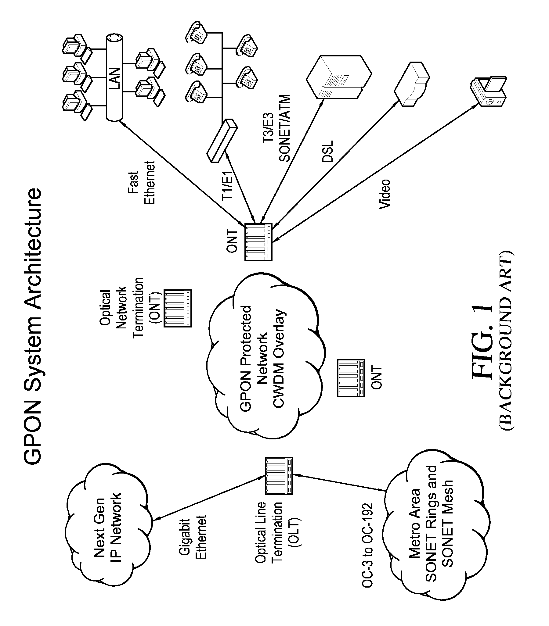
CROSS REFERENCE OF APPLICATION [0001] This application is a continuation of International Patent Application No. PCT / US2006 / 007203, filed on Mar. 2, 2006, which claims priority to U.S. Patent Application No. 60 / 657,424, filed Mar. 2, 2005.BACKGROUND OF THE INVENTION [0002] This present invention relates to a system for sharing data between a plurality of data sources. Specifically, the subject matter of the present invention is directed toward a synchronous apparatus, method and system for data fusion amongst a large number of sensors or other data sources. BACKGROUND OF THE INVENTION [0003]FIG. 1 illustrates an exemplary Gigabit PON (GPON) system architecture of the background art. The GPON backbone enables the network to fully leverage the bandwidth by concatenating many common protocols within a single stream. Furthermore, access to the voice and data streams is transparent to Local Area Network (LAN) technologies such as Fast Ethernet (FE), Gigabit Ethernet (GE), SONET OC-3-OC-1...

Claims


Application Information

Patent Timeline
IPC IPC(8): H04L12/56H04L47/6275
CPCG01D5/00H04B10/00H04J3/06H04L7/00H04Q9/04
Inventor JAMIESON, JOHNMURRAY, JOSEPHJOHNSON, GREGGCAPLAN, SYLVAN I.
Owner 3 PHOENIX
Learn More