
Substrate for semiconductor package

a technology for semiconductors and substrates, applied in the direction of current interference reduction, line-transmission, antennas, etc., can solve the problems of human harm, and the approach may not be able to sufficiently reduce the emi

Inactive Publication Date: 2007-12-13
SAMSUNG ELECTRONICS CO LTD
View PDF10 Cites 21 Cited by
  • Summary
  • Abstract
  • Description
  • Claims
  • Application Information

AI Technical Summary

Benefits of technology

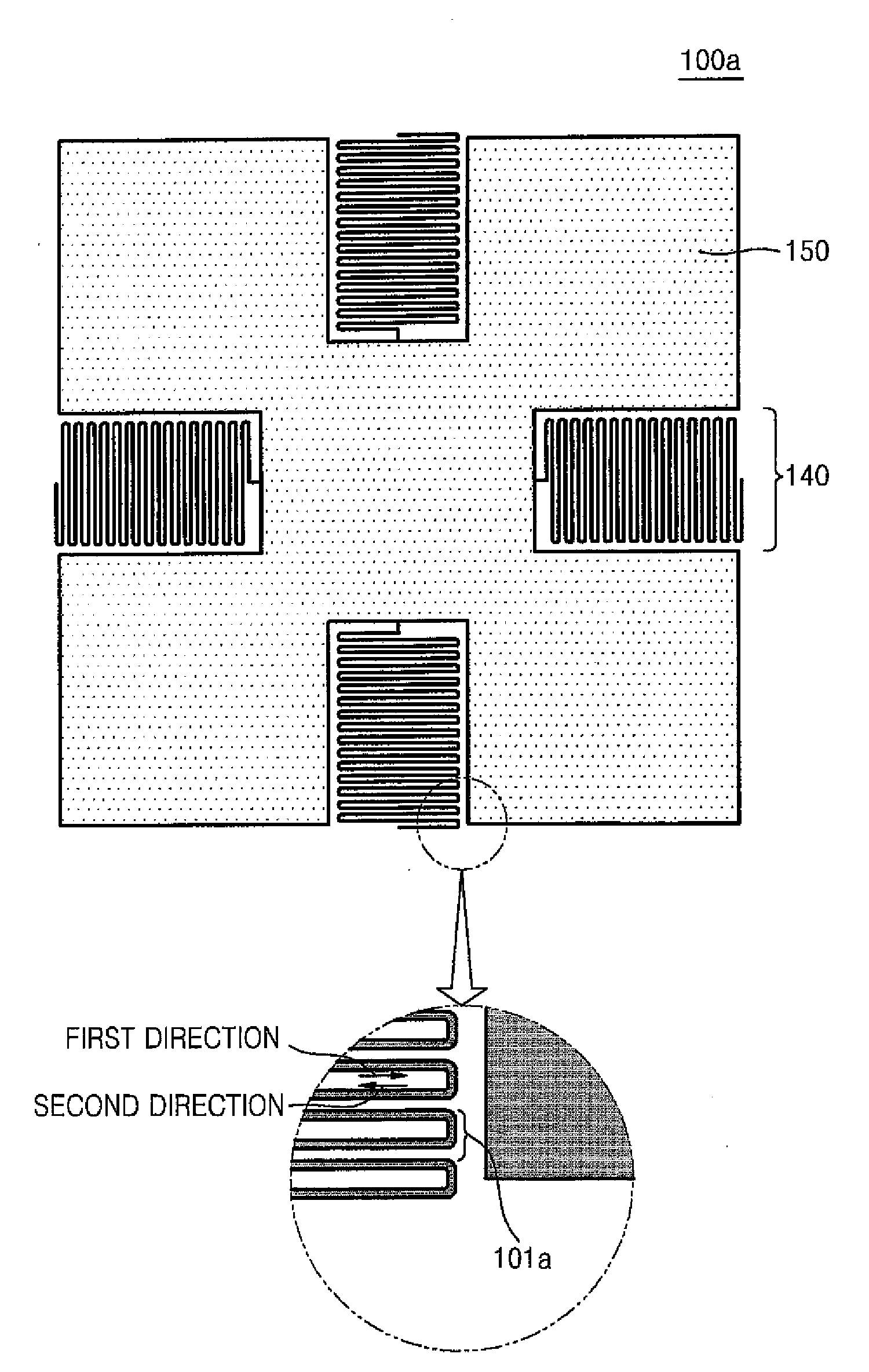
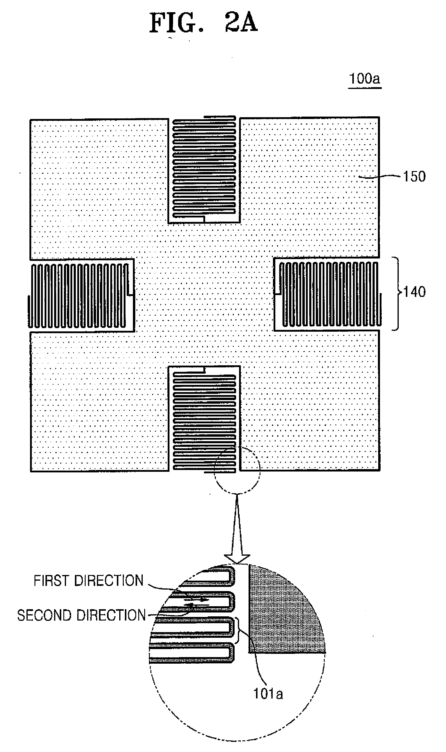
[0012]According to another embodiment of the invention, a substrate for a semiconductor package comprises a stacked dielectric body, a plurality of circuit patterns, and an electromagnetic band gap (EBG) pattern. The stacked dielectric body comprises a plurality of dielectric substrates stacked on each other. The plurality of circuit patterns are formed on at least one of a first surface of the stacked dielectric body, a second surface of the stacked dielectric body, and one or more interface surfaces located at one or more interfaces between adjacent dielectric substrates among the plurality of dielectric substrates, and each of the circuit patterns is connected to ground via a ground connection. The electromagnetic band gap (EBG) pattern comprises a plurality of zigzag unit structures formed on at least one of the first surface, the second surface, and the one or more interface surfaces. Each of the zigzag unit structures comprises a conductor comprising a plurality of zigzag patterns each having portions arranged in two opposing directions, wherein the zigzag patterns are electrically connected to each other, and wherein at least one of the zigzag unit structures is electrically connected to the ground connection.

Problems solved by technology

Unfortunately, these electronic devices tend to generate electromagnetic waves that can cause disruptions in other electronic devices, and in some cases, can even be harmful to human bodies.
Unfortunately, however, this conventional approach may fail to sufficiently reduce the EMI and could benefit from enhancement in several aspects.

Method used


Image

  • Substrate for semiconductor package
  • Substrate for semiconductor package
  • Substrate for semiconductor package

Examples


Embodiment Construction

[0022]Exemplary embodiments of the invention are described below with reference to the corresponding drawings. These embodiments are presented as teaching examples. The actual scope of the invention is defined by the claims that follow.

[0023]In the description that follows, features such as layers may be described as being formed “on” other features such as layers or substrates; however, where this or similar expressions are used to describe the relative positions of features, it should be understood that the features may be in direct contact with each other, or intervening features may also be present.

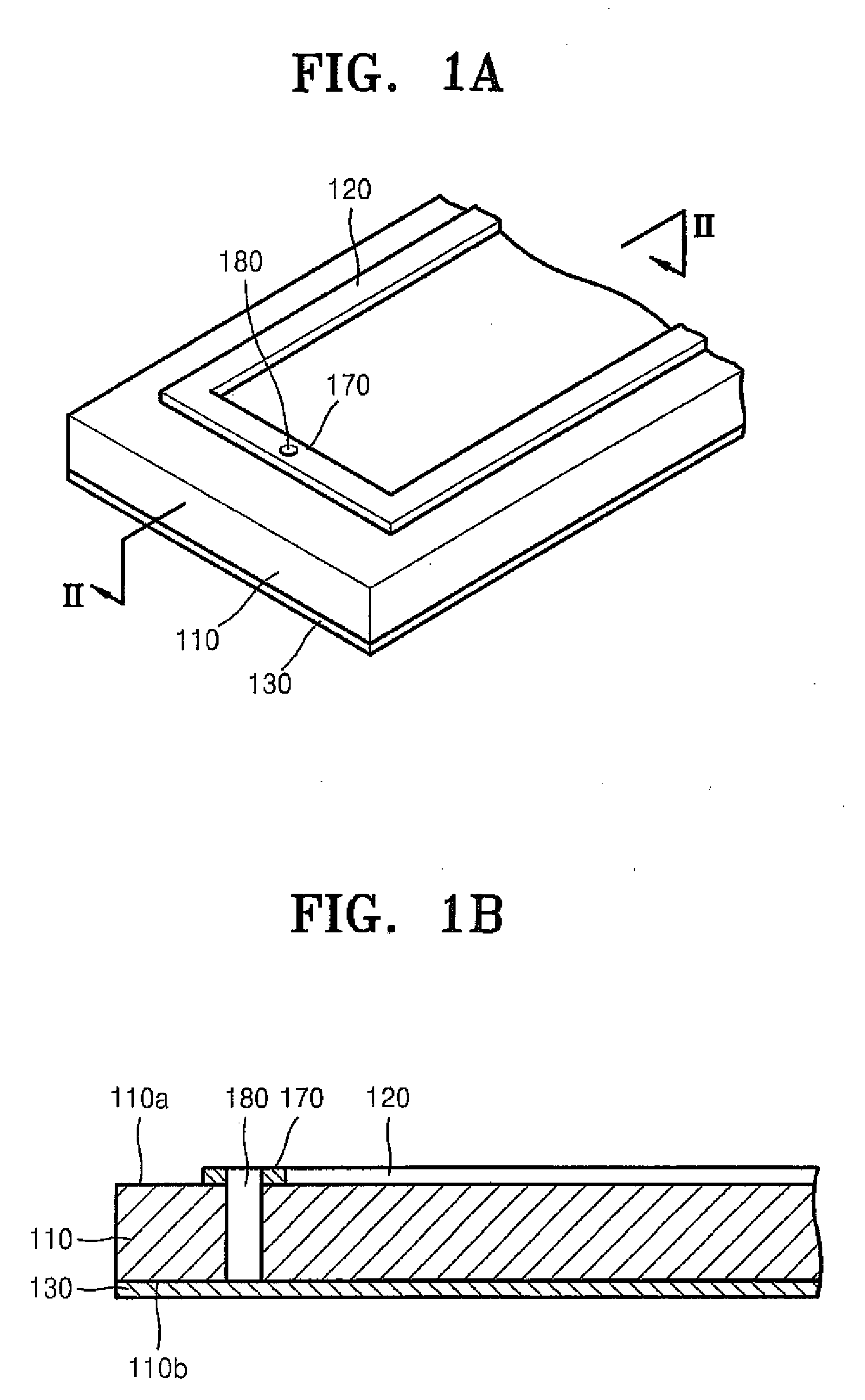
[0024]FIG. 1A is a perspective view illustrating a substrate for a semiconductor package according to an embodiment of the present invention and FIG. 1B is a cross-sectional view taken along a line II-II in the substrate of FIG. 1A.

[0025]Referring to FIGS. 1A and 1B, the substrate comprises a dielectric substrate 110, and a circuit pattern 120 formed on a first surface 110a of dielect...


PUM


Abstract

A substrate for a semiconductor package comprises a dielectric substrate, a circuit pattern, and an electromagnetic band gap (EBG) pattern. The circuit pattern is formed on a first surface of the dielectric substrate and is connected to ground via a ground connection. The electromagnetic band gap (EBG) pattern comprises a plurality of zigzag unit structures formed on a second surface of the dielectric substrate, wherein the second surface is formed on an opposite side of the dielectric substrate from the first surface; the zigzag unit structures are electrically connected to each other; and at least one of the zigzag unit structures is electrically connected to the ground connection.

Description

BACKGROUND OF THE INVENTION[0001]1. Field of the Invention[0002]Embodiments of the invention relate generally to substrates for semiconductor packages. More particularly, embodiments of the invention relate to substrates capable of significantly reducing electromagnetic interference (EMI).[0003]A claim of priority is made to Korean Patent Application No. 10-2006-0053114, filed on Jun. 13, 2006, the disclosure of which is hereby incorporated by reference in its entirety.[0004]2. Description of Related Art[0005]In recent years, electronic devices such as mobile information terminals, cellular telephones, liquid crystal display panels, and notebook computers have continued to get smaller, thinner, and lighter. At the same time, the size and performance of various components within these electronic devices have been adjusted accordingly. For example, semiconductor devices within the electronic devices have become smaller, lighter, and increasingly integrated.[0006]As these electronic de...

Claims


Application Information

Patent Timeline
Patent Type & Authority Applications(United States)
IPC IPC(8): H04B3/28
CPCH01Q15/006H01L23/52
Inventor SONG, EUN-SEOKLEE, HEE-SEOKLIM, SO-YOUNG
Owner SAMSUNG ELECTRONICS CO LTD
Learn More