
Error correction decoding by trial and error

a technology of error correction and decoding, applied in the field of decoding representations of codewords, can solve the problems of less “efficient” ecc schemes, high proportion of memory cells used for parity bits, and high complexity of encoding and decoding

Inactive Publication Date: 2007-12-06
RAMOT AT TEL AVIV UNIV LTD
View PDF10 Cites 58 Cited by
  • Summary
  • Abstract
  • Description
  • Claims
  • Application Information

AI Technical Summary

Benefits of technology

[0035]Preferably, applying the first decoder to the representation of the codeword is faster than applying the second decoder to the representation of the codeword.

Problems solved by technology

But even two algorithms of the same family that both protect the same number of data bits are not necessarily identical.
Typically, protecting against more errors requires the use of more parity bits (or longer codewords), making the ECC scheme less “efficient”, where efficiency is measured by the ratio of the number of data bits in a codeword to the total number of bits in the codeword (including, in systematic ECC, both data bits and parity bits).
The complexity of encoding and decoding is important not only because it affects the speed of the operation, but also because it affects the power consumption and silicon area of hardware implementations of the ECC scheme.
However, the method of Lasser suffers from the drawback that the memory must store the parity bits of both ECC schemes, resulting in a higher proportion of memory cells that are used for parity bits and therefore cannot be used to store real data.
There are also cases in which the most important consideration for the system's designer is the power consumption of the circuitry implementing the decoding process.
Typically, maximal power consumption is related to output reliability—with all other parameters fixed, correcting a larger number of errors typically consumes more power.
However, as the input error rate and the output reliability are usually fixed for the designer, s / he cannot change them for the purpose of minimizing power consumption.

Method used


Image

  • Error correction decoding by trial and error
  • Error correction decoding by trial and error
  • Error correction decoding by trial and error

Examples


Embodiment Construction

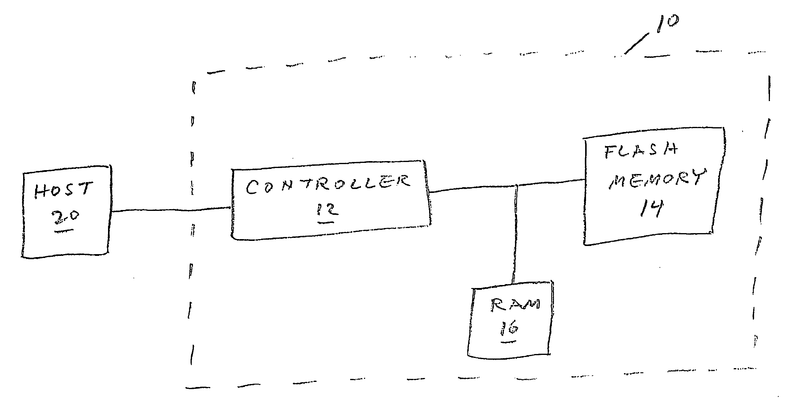
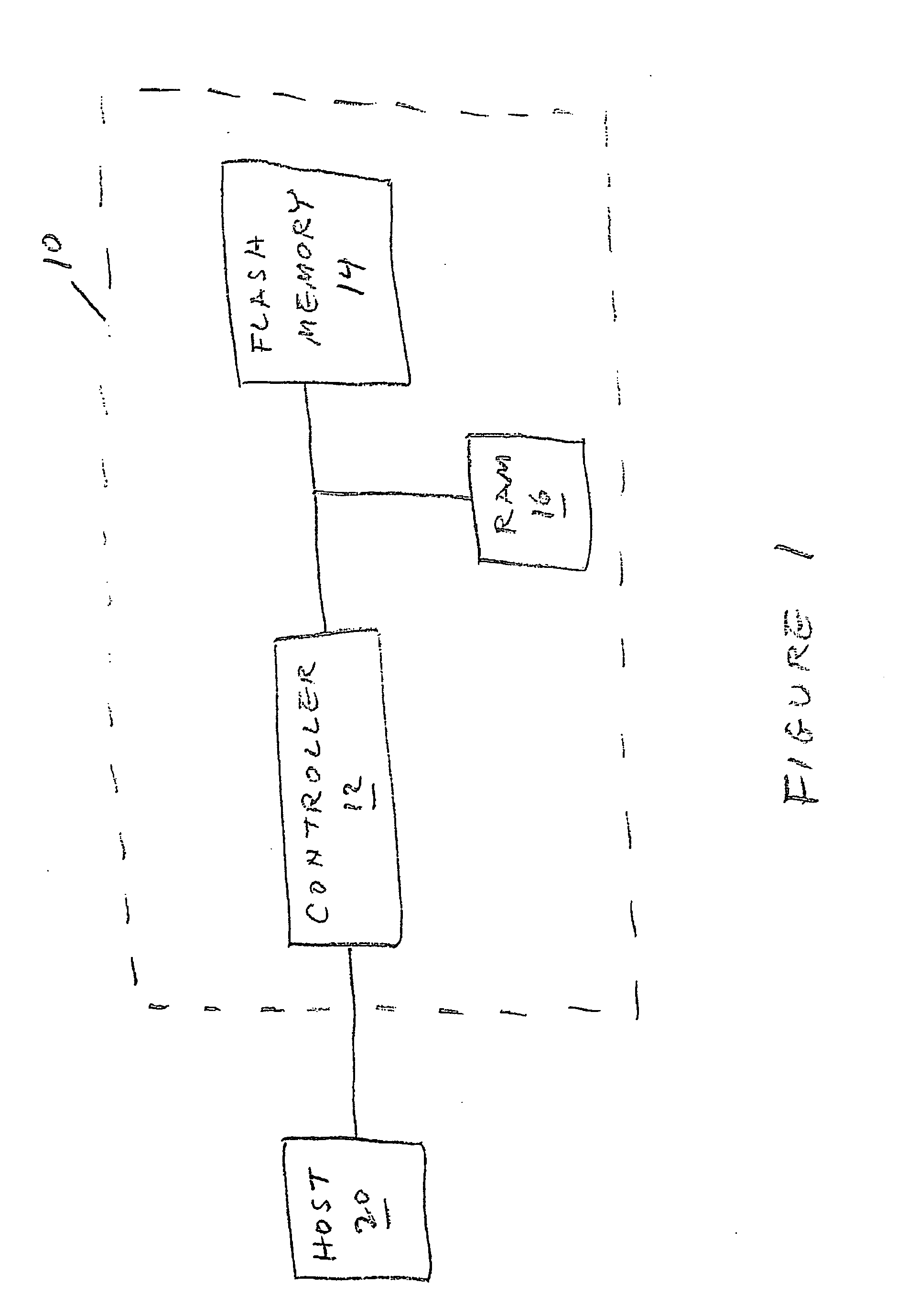
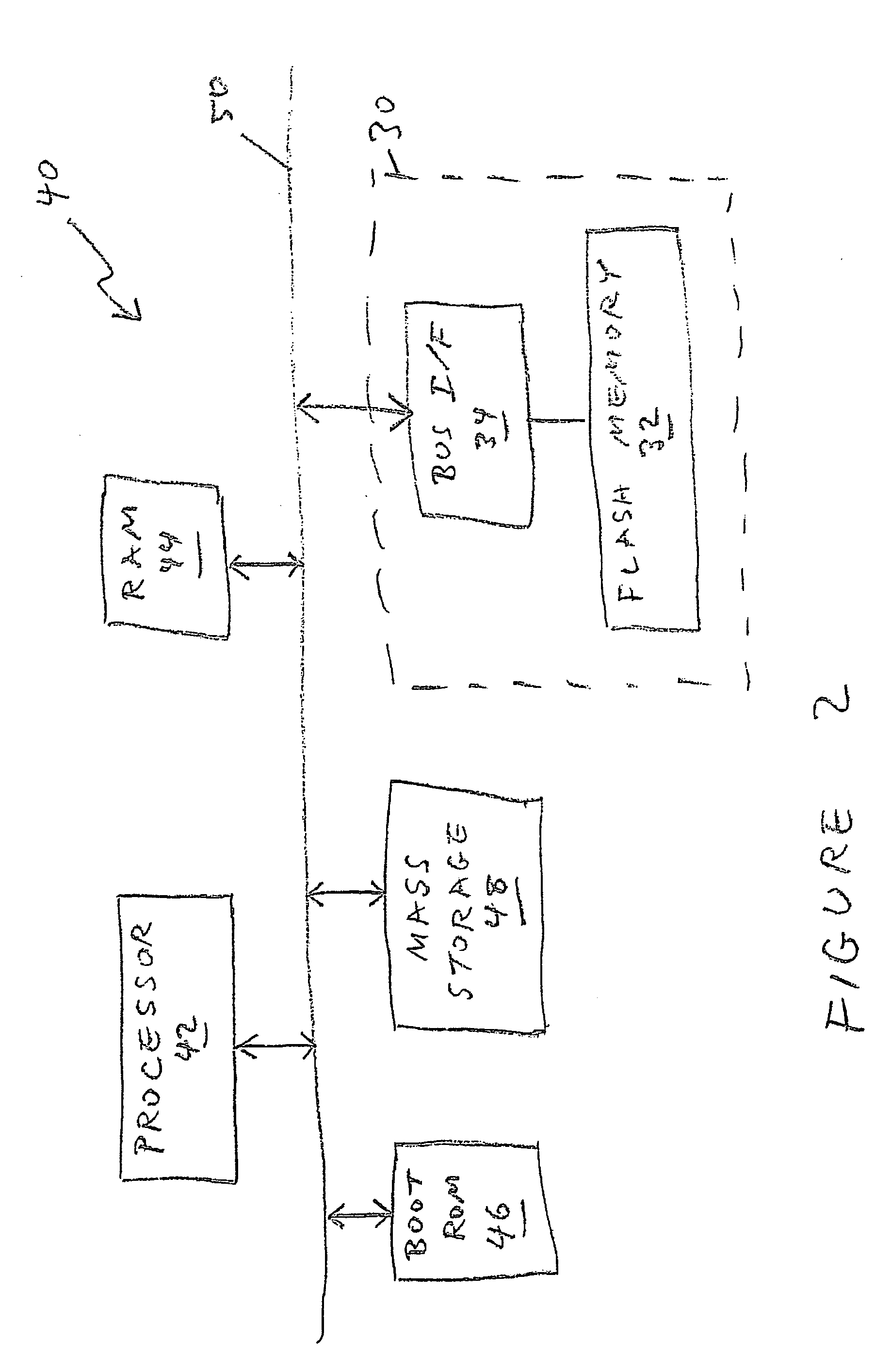
[0048]The principles and operation of error correction decoding according to the present invention may be better understood with reference to the drawings and the accompanying description.

[0049]According to the present invention, two different decoders are used for decoding the same codeword. It should be emphasized that the two decoders operate on the same codeword, containing the same parity bits, and therefore should be considered as two implementations of the same ECC decoding computation.

[0050]The present invention is truly innovative because to one ordinarily skilled in the art this approach would seem useless. Two computations implementing the solution of the same problem should not be expected to bring any advantage over only one computation solving the same problem. However, suppose we have two decoders (or one decoder capable of operating in two different modes) with the following characteristics:[0051]a. The first decoder is fast and consumes little power, but on the othe...


PUM


Abstract

A representation of a codeword is decoded by applying a first decoder of the codeword to the representation of the codeword. If applying the first decoder fails to decode the representation of the codeword then a second decoder of the codeword is applied to the representation of the codeword. Preferably, applying the first decoder consumes less power and is faster than applying the second decoder. Data are ported by encoding the data as a codeword, exporting the codeword to a corrupting medium, importing a representation of the codeword, and applying a first decoder to the representation of the codeword. If applying the first decoder fails to decode the representation of the codeword then a second decoder of the codeword is applied to the representation of the codeword.

Description

[0001]This patent application claims the benefit of U.S. Provisional Patent Application No. 60 / 747,800, filed May 21, 2006FIELD AND BACKGROUND OF THE INVENTION[0002]The present invention relates to the decoding of a representation of a codeword and, more particularly, to a method and related systems for trial-and-error decoding of a representation of a codeword.[0003]Flash memory devices have been known for many years. NAND-type flash memories differ from other types of flash memories (e.g. NOR-type), among other characteristics, by the fact that a certain number of information bits, written to the memory, may be read from the memory in a “flipped” state (i.e. different from the state that the original bits were written to the memory).[0004]In order to overcome this phenomenon and to make NAND-type memories usable by real applications, it is a common technique to use Error Correction Codes (ECC) in conjunction with these memories. A general overview of using ECC in flash memories is...

Claims


Application Information

Patent Timeline
Patent Type & Authority Applications(United States)
IPC IPC(8): H03M13/00
CPCH03M13/3707H03M13/6511H03M13/6502H03M13/3738G06F11/10H03M13/00
Inventor SHARON, ERANALROD, IDANLITSYN, SIMON
Owner RAMOT AT TEL AVIV UNIV LTD
Learn More