Optical disk apparatus

a technology of optical disks and optical disks, applied in the field of optical disk apparatuses, can solve the problems of hardly ensuring the clearance between the turntable and the objective lens on the inner circumference side of the disk, and achieve the effect of smooth labeling

Inactive Publication Date: 2007-12-06
SANYO ELECTRIC CO LTD +1
View PDF7 Cites 7 Cited by
  • Summary
  • Abstract
  • Description
  • Claims
  • Application Information

AI Technical Summary

Benefits of technology

[0016]In view of the foregoing, an object of the invention is to provide an optical disk apparatus which smoothly performs the labeling to the disk while suppressing ...

Problems solved by technology

Therefore, in the case where the two objective lenses are arranged in line in the disk radial direction, there is genera...

Method used


Image

  • Optical disk apparatus
  • Optical disk apparatus
  • Optical disk apparatus

Examples


first example

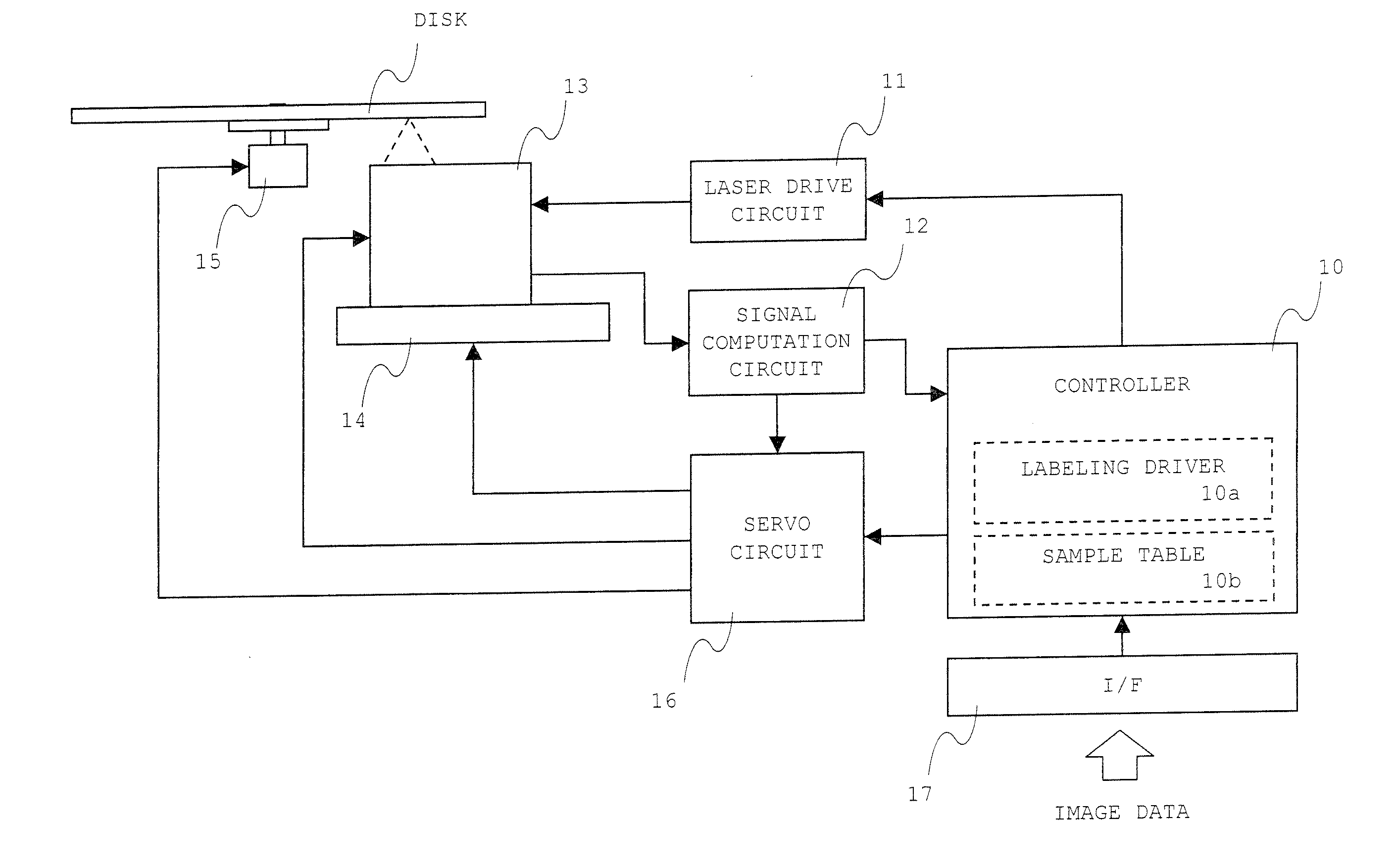
[0041]In this example, the invention is applied to an optical disk apparatus in which the recording and reproduction are performed to the next-generation DVD and CD.

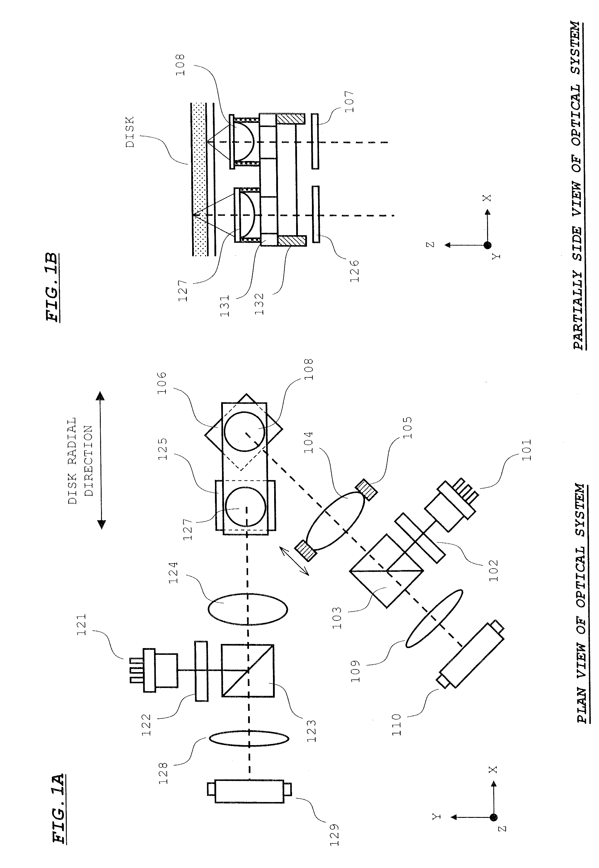
[0042]FIGS. 1A and 1B show an optical system of an optical pickup according to an example. FIG. 1A is a plan view of the optical system and FIG. 1B is a side view showing a neighborhood of an objective lens actuator. The optical system is divided into a next-generation DVD optical system and a CD optical system.

[0043]The next-generation DVD optical system includes a semiconductor laser 101, a diffraction grating 102, a polarization beam splitter 103, a collimator lens 104, a lens actuator 105, a rising mirror 106, a λ / 4 plate 107, a first objective lens 108, an anamorphic lens 109, and a photodetector 110.

[0044]The semiconductor laser 101 emits a blue laser beam having a wavelength of about 400 nm. The diffraction grating 102 divides the laser beam emitted from the semiconductor laser 101 into three beams. The polarizati...

second example

[0083]In this example, the invention is applied to an optical disk apparatus in which the recording and reproduction are performed to the next-generation DVD, DVD, and CD.

[0084]FIGS. 8A and 8B show an optical system of an optical pickup according to this example. FIG. 8A is a plan view of the optical system and FIG. 8B is a side view showing a neighborhood of an objective lens actuator. The optical system is divided into a next-generation DVD optical system and a CD / DVD optical system.

[0085]The CD / DVD optical system includes the diffraction grating 122, the polarization beam splitter 123, the collimator lens 124, the rising mirror 125, the anamorphic lens 128, and the photodetector 129, a semiconductor laser 144, and a second objective lens 145. The semiconductor laser 144 emits the laser beam having the infrared wavelength of about 780 nm and the laser beam having the red wavelength of about 650 nm. The second objective lens 145 converges the laser beam having the infrared waveleng...


PUM


Abstract

Two objective lenses are attached to a common holder. The holder is driven by an objective lens actuator, which integrally drives the two objective lenses. At this point, the objective lens (first objective lens) having a smaller diameter is arranged on a disk inner circumference side. In labeling, a reference pattern located at an inner circumference position is irradiated with a laser beam through the inner circumference-side first objective lens to obtain a gain which is used to finely move an objective lens actuator in a disk radial direction. The disk is irradiated with the laser beam through the second objective lens to generate an image in a disk surface while the objective lens actuator is driven with the gain.

Description

[0001]This application claims priority under 35 U.S.C. Section 119 of Japanese Patent Application No. 2006-155594 filed Jun. 5, 2006.BACKGROUND OF THE INVENTION[0002]1. Field of the Invention[0003]The present invention relates to an optical disk apparatus in which labeling is performed to an optical disk using a laser beam outgoing from an optical pickup, particularly to the optical disk apparatus provided with a compatible optical pickup including plural objective lenses.[0004]2. Description of the Related Art[0005]Currently, there are known various techniques as an optical disk labeling technique. Among others, the optical disk labeling technique with a laser beam emitted from an optical pickup is used as the labeling technique for CD (Compact Disc) and DVD (Digital Versatile disc).[0006]In the labeling technique, the optical disk is loaded on a disk drive while a right surface in recording / reproduction is reversed. When a user inputs a desired image, a disk surface labeling drive...

Claims


Application Information

Patent Timeline
IPC IPC(8): B41J2/455
CPCB41J2/442B41J3/4071G11B7/0037G11B7/08505G11B2007/0006G11B7/1376G11B7/13925G11B23/40G11B7/1374G11B7/085
Inventor ASANO, KENJI
Owner SANYO ELECTRIC CO LTD
Why Eureka
Try Eureka