Integrated differential oscillator circuit

a differential oscillator and circuit technology, applied in oscillator technology, pulse generators, pulse techniques, etc., can solve the problems of relative large dispersion of resistance values, and achieve the effects of improving signal-to-noise ratio, wide tuning range, and high quality

Inactive Publication Date: 2007-12-06
ATMEL GERMANY
View PDF8 Cites 6 Cited by
  • Summary
  • Abstract
  • Description
  • Claims
  • Application Information

AI Technical Summary

Benefits of technology

[0010] It is therefore an object of the present invention to provide an integrated differential oscillator circuit with an improved signal-to-noise ratio, a relatively wide tuning range and / or a relatively high quality, a relatively high efficiency and relatively small effects from production-related variations on the circuit characteristics.
[0016] In contrast, as a result of the inventive connection of the input of the amplifier circuit to the second DC voltage of the DC power supply through the second inductor and the second DC path, a very low resistance of the DC power supply is achieved overall. Because of the differential design, separate DC path sections to the terminals of the differential input are still necessary. However, these sections are implemented through the extremely low resistance inductors. The total resistance of the DC power supply is thus dominated at the input side of the amplifier arrangement by components such as resistors or transistors of a current source of the DC power supply, which components are arranged in a circuit section that is common to both terminals of the differential input. As a result of these influences, asymmetries in the DC power supply of the amplifier circuit are avoided almost completely.

Problems solved by technology

By contrast, in the customary DC connection of the amplifier circuit with the aid of resistors of semiconductor material or with the aid of active current sources or current sinks that contain transistors, process variations result in relatively large dispersions in the resistance values.

Method used


Image

  • Integrated differential oscillator circuit
  • Integrated differential oscillator circuit
  • Integrated differential oscillator circuit

Examples


Embodiment Construction

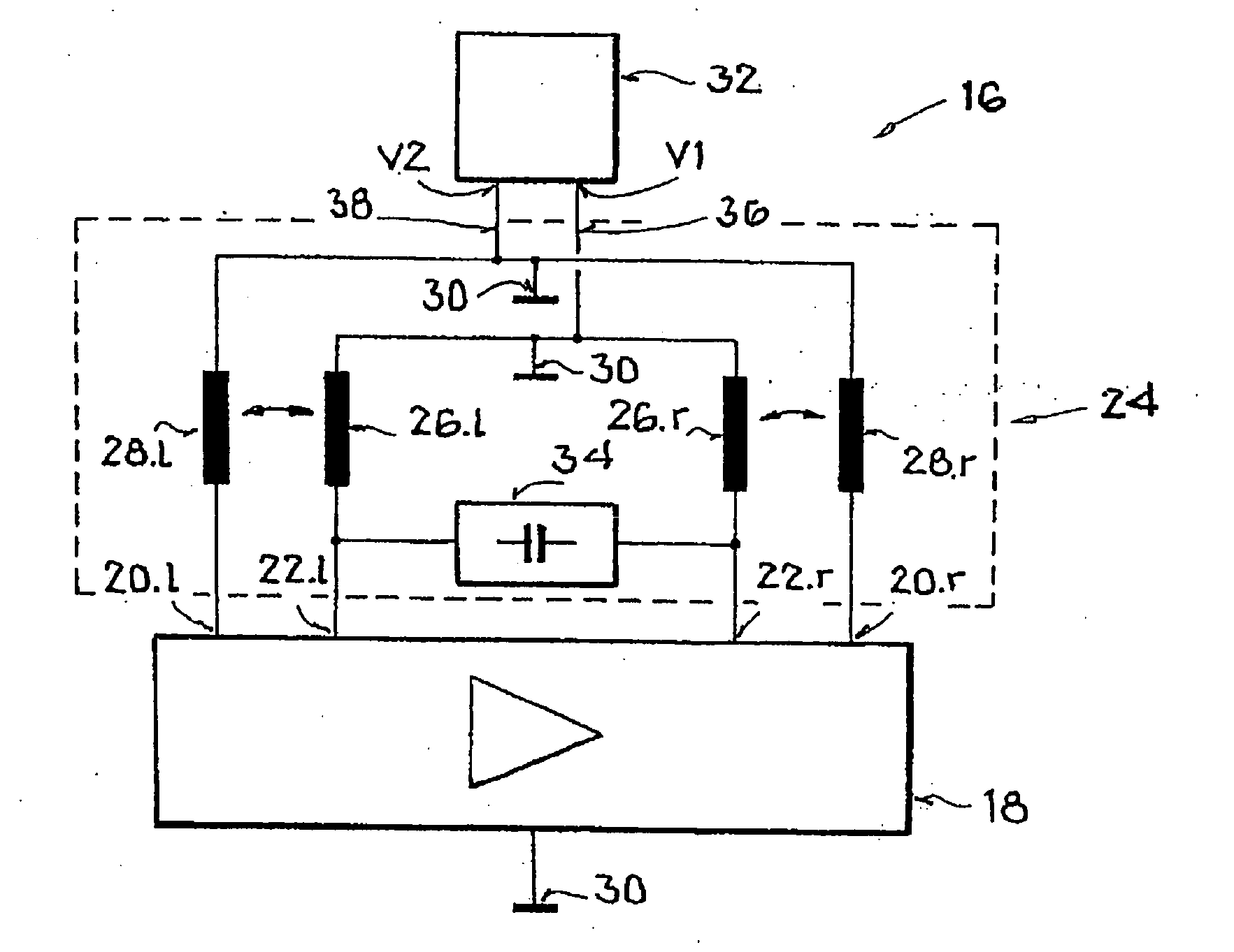
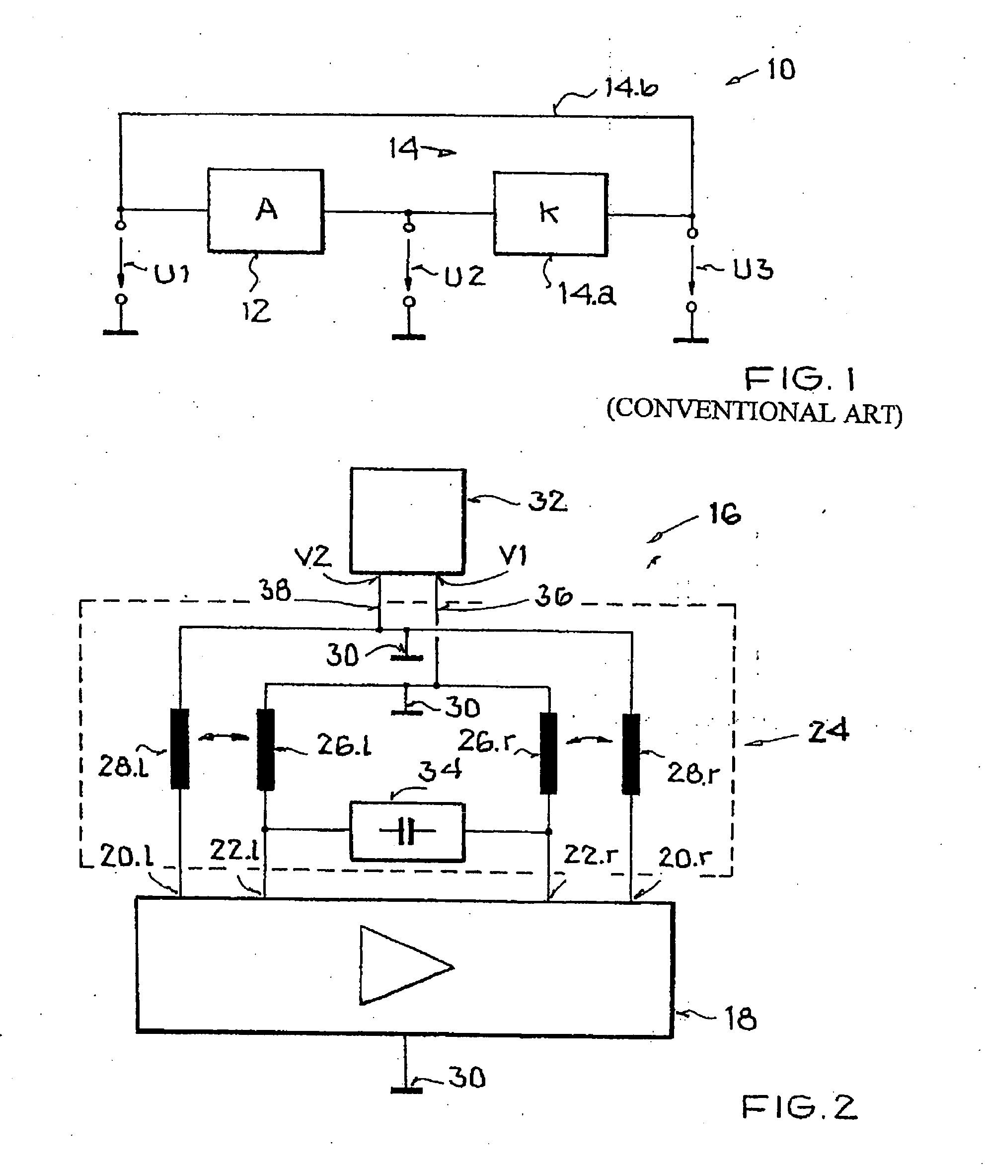
[0032] In this connection, like elements are labeled with like reference symbols in all figures. Specifically, FIG. 1 shows the known principle of a feedback oscillator circuit 10, which circuit in general has an amplifier circuit 12 with a frequency-selective feedback network 14. The amplifier circuit amplifies an input signal U1 into an output signal U2=A*U1. The feedback network 14 selects a resonant frequency from the output signal U2 and feeds the output signal of the selected frequency back to the input in attenuated form as the signal U3=k*U2. As is known, a stable oscillation of the output signal U2 is established when the amplitude of the feedback signal U3 is equal to the amplitude of the input signal U1. If the product of the gain A and attenuation k is defined as the loop gain g, then g must be equal to 1. Moreover, the phase shift between U1 and U3 must permit a constructive interference, and thus in the ideal case must be an integer multiple of 2π. These relationships ...


PUM


Abstract

An integrated differential oscillator circuit is provided, which has an amplifier circuit with an input and an output, a frequency-selective feedback network with a first inductor and a second inductor, and a DC power supply. The oscillator circuit is distinguished in that the output is transformer-coupled to the input through the first inductor and the second inductor of the feedback network, wherein the output is connected to a first DC voltage through the first inductor and a first DC path, and the input is connected to a second DC voltage of the DC power supply through the second inductor and a second DC path.

Description

[0001] This nonprovisional application claims priority under 35 U.S.C. § 119(a) on German Patent Application No. DE 102006017188, which was filed in Germany on Apr. 12, 2006, and which is herein incorporated by reference. BACKGROUND OF THE INVENTION [0002] 1. Field of the Invention [0003] The present invention relates to an integrated differential oscillator circuit which has an amplifier circuit with an input and an output, and has a frequency-selective feedback network with a first inductor and a DC power supply. [0004] 2. Description of the Background Art [0005] An oscillator circuit is known from WO 99 / 43079, which corresponds to U.S. Pat. No. 6,002,303. This document shows a differential oscillator design with two resonant circuits that are deattenuated through an amplifier circuit of two transistors in common-base configuration. In the terminology of WO 99 / 43079, the first resonant circuit has a first resonant element, a first feedback path, and a differential coupling element...

Claims


Application Information

Patent Timeline
IPC IPC(8): H03B5/12H03B5/24
CPCH03B5/1841H03B5/1231H03B5/124H03B5/1218H03B5/1212
Inventor EL RAI, SAMIRTEMPEL, RALF
Owner ATMEL GERMANY
Why Eureka
Try Eureka