Control And Power Module For A Rotating Electrical Machine

a technology of control and power module, which is applied in the direction of control system, electrical apparatus, field or armature current control, etc., can solve the problems of high overvoltage increased dc voltage of the on-board system, and drop in current consumption on the on-board system sid

Inactive Publication Date: 2007-12-06
VALEO EQUIP ELECTRIC MOTEUR
View PDF30 Cites 12 Cited by
  • Summary
  • Abstract
  • Description
  • Claims
  • Application Information

AI Technical Summary

Benefits of technology

[0020] Thus the locking of at least one branch of the power circuit has the effect of reducing the current generated by the alternator. This makes it possible to make the voltage on the on-board system drop, because of the consumption of current by the electrical equipment that remained connected to it, whilst waiting for the regulation to adapt the excitation current injected into the field winding of the machine.
[0027] In a non-limiting embodiment, the control circuit is adapted so as, when a branch is locked, to maintain the said branch in a first conduction state for part of the locking time and to maintain the said branch in a second conduction state during the rest of the locking time. This embodiment makes it possible to distribute the thermal dissipation between the components of one branch, and this in alternation. This thus limits heating thereof.
[0029] In a non-limiting embodiment, the control circuit is adapted to maintain all the branches of the power circuit that are locked in the same conduction state. This makes it possible to short-circuit one or more phase windings and therefore to reduce the current generated by the machine.
[0032] Advantageously, the present invention does not add any electronic components. In addition it makes it possible to maintain the power supply to the electrical components of the on-board system in the event of load dump.

Problems solved by technology

This is because, since a regulation of an inducing current in the machine cannot act sufficiently quickly following the load dump, the machine continues to deliver the same output current whereas the current consumption on the on-board system side has dropped.
Nevertheless, in the event of disconnection of the battery (due to the breakage of a supply cable, for example), a very high overvoltage may occur on the on-board system.
This is because the current delivered by the machine charges the capacitances (including the stray capacitances) connected to the on-board system, and consequently causes the DC voltage of the on-board system to increase significantly.
This overvoltage risks damaging the electrical equipment supplied by the on-board system.
Thus, in the event of load dump, the limitation of the voltage of the on-board system is guaranteed by the power transistors constituting the switches of the bridge rectifier going into avalanche.
These known solutions have certain advantages but are imperfect in the context of the future use of batteries of larger capacity, for example 42 volts, in vehicles, made necessary by the tendency towards the increase in electrical equipment with high energy consumption.
However, the limitation voltage or clipping voltage of MOSFET transistors is too high (above 58V) and is not sufficiently controlled to enable them to be used in this context.
In addition, in the case of the use of Zener diodes with MOS transistors, they must be able to absorb currents of several hundreds of amperes, giving rise to significant bulk and additional cost since it is necessary to add several of them.

Method used


Image

  • Control And Power Module For A Rotating Electrical Machine
  • Control And Power Module For A Rotating Electrical Machine
  • Control And Power Module For A Rotating Electrical Machine

Examples


Embodiment Construction

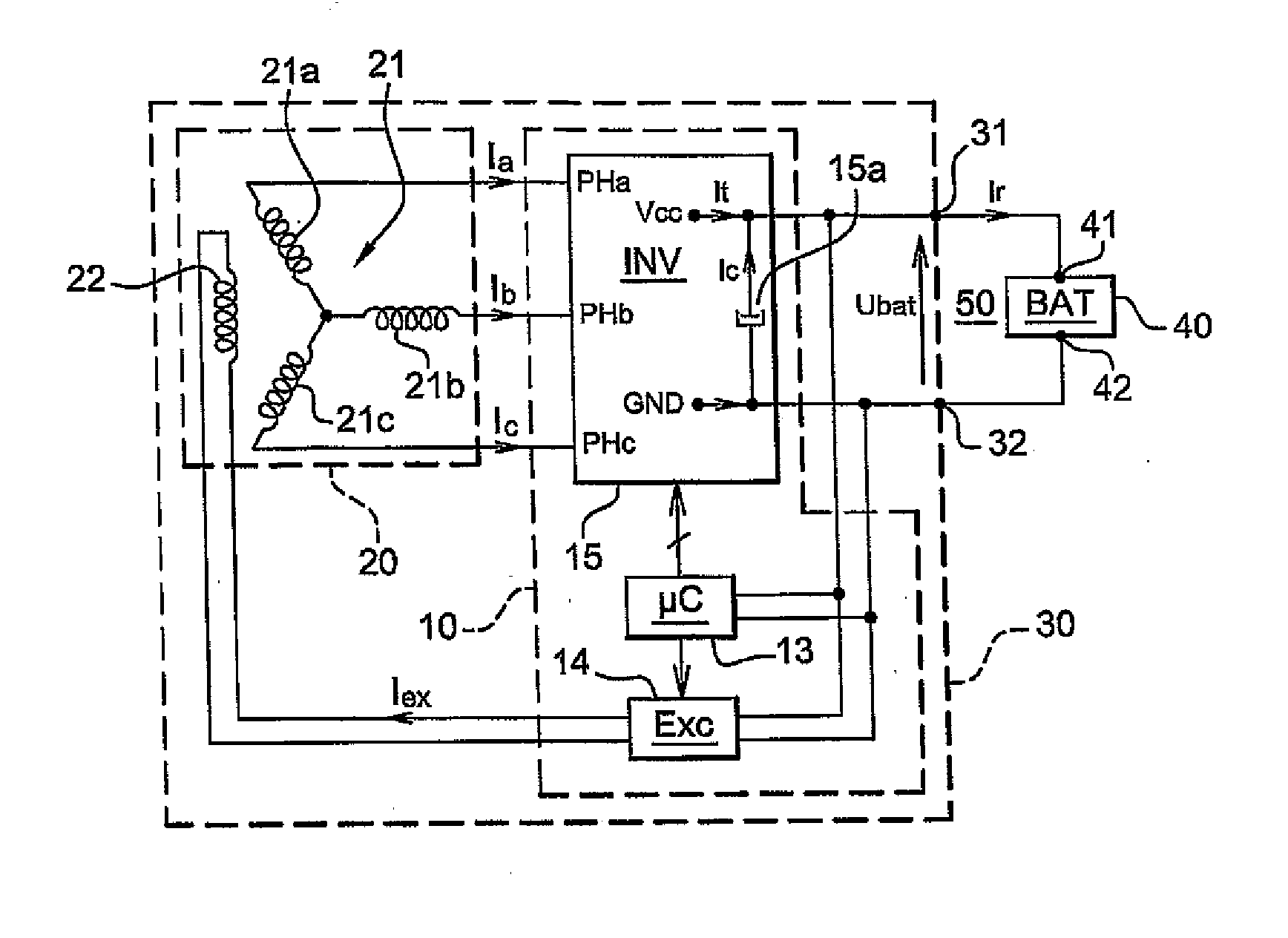
[0049] The present invention will now be described in the context of its application to the control of a polyphase rotary electrical machine such as one of those mentioned in the introduction. Here the concern is only with the mode of functioning as an alternator of these machines. This mode is the only operating mode for an alternator. It is one of the possible operating modes for machines of other types. For the remainder of the description, the non-limiting example of an alternator / starter 30, a reversible machine, will be taken.

[0050] Moreover, for the remainder of the description, electrical equipment may be termed indifferently consumers or loads.

[0051] An alternator / starter 30 comprises three operating modes. An idle mode, an alternator mode, also referred to as generator mode, and a motor mode comprising a starting mode, known to persons skilled in the art.

[0052]FIG. 1 shows schematically an alternator / starter 30 according to the invention. The alternator / starter 30 is in...


PUM


Abstract

A control and power module for a rotating electrical machine comprising a power circuit containing a number of branches, and a control circuit designed for controlling the power circuit when the machine operates in a nominal mode. The inventive module is characterized in that the control circuit is also designed for monitoring an output voltage from the power circuit and blocking at least one branch of the power circuit in a conduction state when the output voltage reaches an at least first threshold value so that the machine functions in a degraded mode. The invention is for use in an alternator starter.

Description

FIELD OF THE INVENTION [0001] The present invention concerns in general terms the protection of electrical systems against load dump. It applies in particular in the automobile field. PRIOR ART [0002] In a motor vehicle, an electrical system, referred to as an “on-board system”, serves to supply the electrical equipment with which the vehicle is equipped. Such an on-board system can be assimilated to a DC supply bus. The supply is provided by at least one battery. The latter is recharged by virtue of a rotary electrical machine, from the energy supplied by the rotation of the thermal engine of the vehicle. The rotary electrical machine means more generally any single- or polyphase rotary electrical machine for producing output DC current supplying the on-board system. It may in particular be an alternator or an alternator / starter. [0003] In the event of abrupt disconnection of an electrical load in the on-board system, or of a battery, or both, a phenomenon of load dump (“load-dump”...

Claims


Application Information

Patent Timeline
IPC IPC(8): H02H7/06H02P9/10
CPCH02P7/00H02P9/102H02P2101/45H02P2101/30H02H7/067
Inventor CHEMIN, MICHAELBERNARD, FRANCOIS-XAVIERLEROUX, FREDERIC
Owner VALEO EQUIP ELECTRIC MOTEUR
Why Eureka
Try Eureka