
Method and apparatus for stripping voltammetric and potentiometric detection and measurement of contamination in liquids

a technology of potentiometric and voltammetric detection, applied in the direction of liquid/fluent solid measurement, material electrochemical variables, instruments, etc., can solve the problems of high cost of instrumentation, frequent maintenance and calibration, and inability to accurately determine the activity of electrochemically active ions in the aqueous solution,

Inactive Publication Date: 2007-12-06
INT TECH ASSOC
View PDF1 Cites 20 Cited by
  • Summary
  • Abstract
  • Description
  • Claims
  • Application Information

AI Technical Summary

Benefits of technology

The patent describes a sampling system for measuring the presence and concentration of inorganic ions in a liquid solution. The system includes a potentiometric subsystem for measuring environmental metrics of the sample, a preparation subsystem for isolating contaminants of concern, and a voltammetric subsystem for identifying and determining the concentration of metal, metalloid, or non-metal ions through stripping voltammetry. The system can compare the stripping signal of the sample with a predetermined value to determine if dilution of the sample is required. The technical effect of this patent is to provide a reliable and accurate method for detecting and identifying the concentration levels of metal, metalloid, or non-metal ions in liquid samples.

Problems solved by technology

For example, mercury is regarded as a very toxic heavy metal, and its presence in soil and waterways represents a considerable health hazard.
However, they often require well-controlled experimental conditions, expensive instrumentation, and frequent maintenance and calibration.
Moreover, these methods usually require lengthy sample preparation, especially when other interfering elements or impurities are present in the sample under investigation.
For these reasons, the methods mentioned above are not particularly well-suited for rapid analysis in the field or on-site in a treatment plant.
However, the detection limits for this method (about 30-100 ppm) is not low enough for accurately determining very low levels of metals like mercury (2 ppb).
Colorimetric techniques can be complicated and time-consuming.
One significant disadvantage of most commonly used methods in the detection of trace contaminants is the difficulty of performing analyses of highly complex samples, such as ocean water.
In complex solutions there can be a wide variety of elements with concentration levels much higher than the contaminants of concern which often interfere with the accurate detection and quantification of trace elements.
The concentration difference between the contaminants of concern and the other impurities in the water precludes the successful application of many analytical tools and techniques.
Presently, many common methods frequently require extensive sample pretreatment to determine low impurity levels of highly complex samples.
Thus, prior art systems are mostly for laboratory use, labor intensive and require considerable supervision by skilled personnel in order to determine low levels of contaminant concentrations.
Furthermore, conventional techniques are impaired by interference caused by high concentrations of other species present with the impurities.
While this technique decreases interference problems, it significantly complicates the design of the system and algorithm of measurements.
Also, additional steps of removing the sample from the cell after deposition of electrochemically active species and pumping electrolyte to the cell may cause unwanted changes on the electrode surface, which decreases the accuracy and precision of the analysis, thereby increasing the time of the analysis.

Method used


Image

  • Method and apparatus for stripping voltammetric and potentiometric detection and measurement of contamination in liquids
  • Method and apparatus for stripping voltammetric and potentiometric detection and measurement of contamination in liquids
  • Method and apparatus for stripping voltammetric and potentiometric detection and measurement of contamination in liquids

Examples


Embodiment Construction

(s)

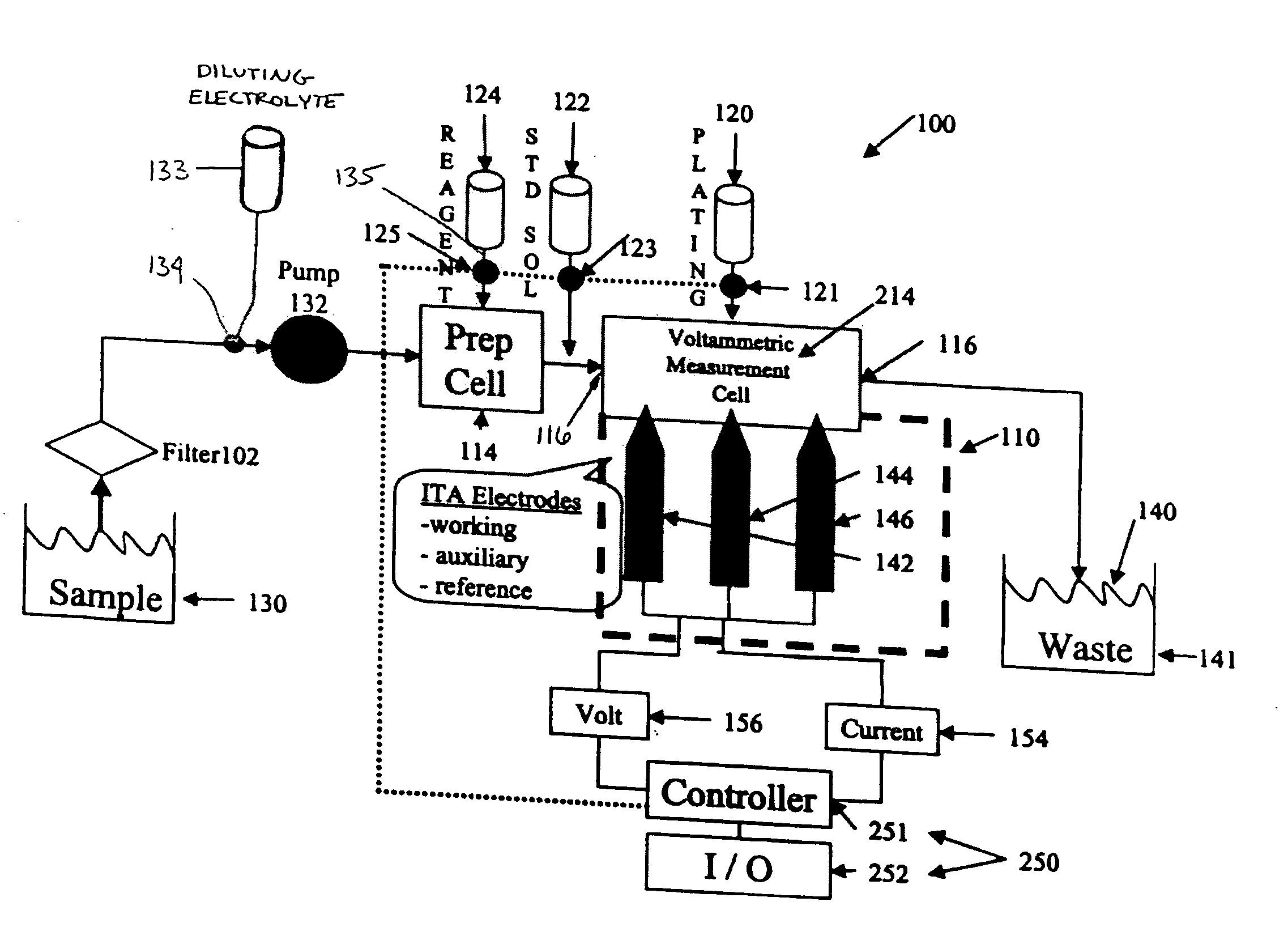
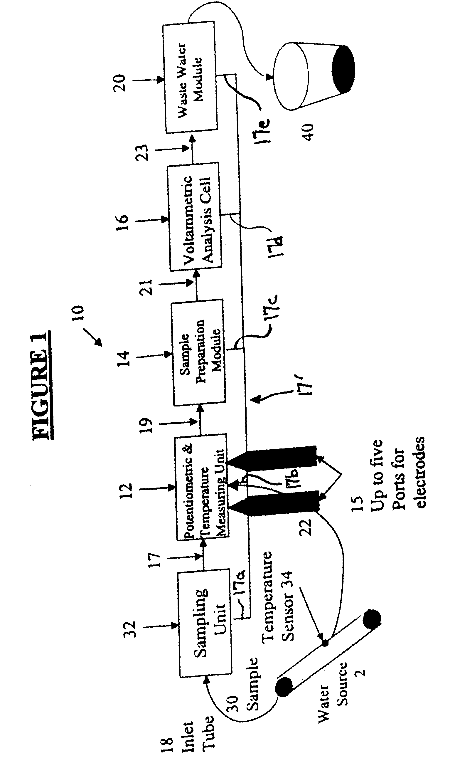
[0034] Referring to FIG. 1, a block diagram of a system 10 incorporating features of the exemplary embodiments is shown. Although the exemplary embodiments will be described with reference to the embodiments shown in the drawings, it should be understood that the exemplary embodiments can be embodied in many alternate forms of embodiments. In addition, any suitable size, shape or type of elements or materials could be used.

[0035] The system 10 and process disclosed herein have a more innovative, capable and simple design. Different electrode types may be employed, e.g. gold plated electrode, in order to increase the sensitivity and selectivity of the analysis. The measurement cell design disclosed herein provides for significantly more stable electrodes that, when used with the proposed analysis technique will result in lower detection capability and faster analysis times which are critical to the on-line process control applications intended for this system.

[0036] The system 1...


PUM

PropertyMeasurementUnit
concentrationaaaaaaaaaa
deposition potentialaaaaaaaaaa
depositionaaaaaaaaaa

Abstract

A sampling system for measuring the presence and concentration of inorganic ion species, including, metals, metalloids and non-metals, in a liquid solution including a first sampling unit. The first sampling unit includes a potentiometric subsystem configured to gather environmental metrics of the liquid sample, a preparation subsystem, coupled to the potentiometric module, the preparation subsystem being configured to prepare and isolate contaminants of concern in a flow of a liquid sample into metal, metalloid, or non-metal ionic forms; and a voltammetric subsystem selectively coupled to the preparation subsystem, potentiometric subsystem and a sample source, the voltammetric subsystem being configured to identify and determine a concentration of metal, metalloid, or non-metal ionic species through stripping voltammetry. The system is configured to compare a value of a stripping signal of the sample with a predetermined value to determine if dilution of the sample is required.

Description

CROSS-REFERENCE TO RELATED APPLICATIONS [0001] This application is a continuation in part of application Ser. No. 10 / 125,822 entitled “METHOD AND APPARATUS FOR STRIPPING VOLTAMMETRIC AND POTENT IOMETRIC DETECTION AND MEASUREMENT OF CONTAMINATION IN LIQUIDS”, filed on Apr. 19, 2002, which claims priority from U.S. Provisional Application No. 60 / 299,514, filed on Jun. 19, 2001.BACKGROUND [0002] 1. Field [0003] The exemplary embodiments generally relate to water processing and treatment, and more particularly, to the determination of electrochemically active ions in an aqueous solution. [0004] 2. Brief Description of Related Developments [0005] In recent years there has been increasing demand for continuous real-time or near real-time monitoring of solution composition. Of particular interest are voltammetric detectors which measure the current response at given applied potential. Voltammetric detectors have applications which cover many fields and include for example environmental mon...

Claims


Application Information

Patent Timeline
Patent Type & Authority Applications(United States)
IPC IPC(8): G01N27/48G01N27/416G01N27/42G01N33/18
CPCG01N27/4166G01N33/1893G01N33/1813
Inventor VILTCHINSKAIA, ELENAWITHERS, PETER A.
Owner INT TECH ASSOC
Learn More