
Phototherapy Systems And Methods

a technology of phototherapy and systems, applied in the field of phototherapy systems, can solve the problems of increasing the visibility of skin lines and wrinkles, the inability to implement indoor tanners, and the difficulty in controlling the quality of ultra-violet light exposure by the sun

Inactive Publication Date: 2007-11-29
LEDEEP
View PDF56 Cites 99 Cited by
  • Summary
  • Abstract
  • Description
  • Claims
  • Application Information

AI Technical Summary

Problems solved by technology

Health research has shown that both the condition of under-exposure to ultra-violet light and the condition of over-exposure to ultra-violet light causes a variety of health problems.
The quality of ultra-violet light exposure by the sun is not simple to control.
Indoor-tanning does not implement systems that are directly dependent on the sun as the source of ultra-violet radiation.
UVB skin tanning has, what some tanners consider, an additional negative effect, UVB tanning will thicken the second layer of skin and as a result increases the visibility of skin lines and wrinkles.
UVB tanning creates a shedding cycle of 5 to 7 days which is undesirable when a UVA tan has a shedding cycle of 28 days.
However, UVB light can also degrade Vitamin-D.
In exceptional conditions such as albinism, the third layer of skin is not capable of producing melanin.
It is common knowledge that all wavelengths of UV over long exposure periods damages the skin in various ways.
Therefore, it has been recommended by various health organizations studying the phenomena that moderate exposure to UV light has a net health benefit, whereas over-exposure or under-exposure of UV results in a net health deficit.

Method used


Image

  • Phototherapy Systems And Methods
  • Phototherapy Systems And Methods
  • Phototherapy Systems And Methods

Examples


third embodiment

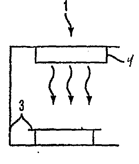
[0071] In a third embodiment shown in FIG. 8A, the UV light emitting device (4) comprises a plurality of layers of nanoparticles or nanowires arranged in a direction extending from the UV excitation radiation source (7) to the portion of the chamber (3) which houses the person undergoing phototherapy. The nanoparticles or nanowires in each layer emit radiation having a different peak wavelength from the nanoparticles or nanowires in other layers. Preferably, the peak wavelength of the UV radiation emitted by the nanoparticles or nanowires increases in each subsequent layer in the direction from the UV excitation source (7) to the portion of the chamber (3) which houses the person undergoing phototherapy. In other words, the nanoparticles or nanowires in each layer located closer to the person's skin (i.e., farther from the UV excitation source (7)) emit radiation of a longer wavelength that those in another layer located farther from the person's skin (i.e., closer to the UV excitat...

fourth embodiment

[0075] In the present invention shown in FIG. 9, an optical filter (150) is located between the UV excitation source (7) and the UV light emitting device (4). The filter (150) is transparent to the shorter wavelength UV excitation radiation from source (7). However, the filter (150) reflects UV light of a longer peak wavelength emitted by the UV light emitting device (4). The filter (150) may be a holographic filter or any other suitable filter having the above described property. This configuration is advantageous when nanoparticles are used as the light emitting device (4). The nanoparticles emit UV light in all directions. However, the filter (150) reflects UV light emitted toward the source (7) back in the direction of the portion of the chamber (3) in which the person is to be located.

[0076] The fifth embodiment is a combination of the third and fourth embodiments. As shown in FIG. 10, the UV light emitting device (4) comprises a plurality of layers (110), (130) of nanoparticle...

seventh embodiment

[0079] In a seventh embodiment, the system (1) contains the UV light emitting device (4) with exchangeable nanoparticles or nanowires to vary the peak emission wavelength of the device (4). For example, if the nanoparticles are located in a suspension in a sealed vessel, then the vessel may be opened and the suspension replaced by another suspension having nanoparticles which emit light of a different wavelength from the nanoparticles in the original suspension. Preferably, the vessel comprises non-stick surfaces to prevent nanoparticle adhesion. Alternatively, the entire vessel housing the suspension may be removed from the system and replaced with another vessel containing a different suspension of different nanoparticles which emit light of a different peak wavelength than the nanoparticles of the original suspension. If the nanoparticles or nanowires are coated as a solid layer on a substrate or substrates, then the substrate or substrate may be easily removable from the system ...


PUM


Abstract

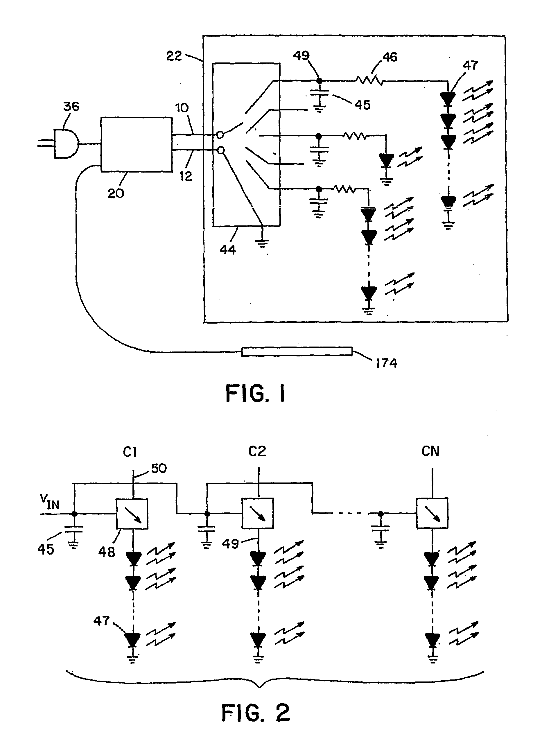
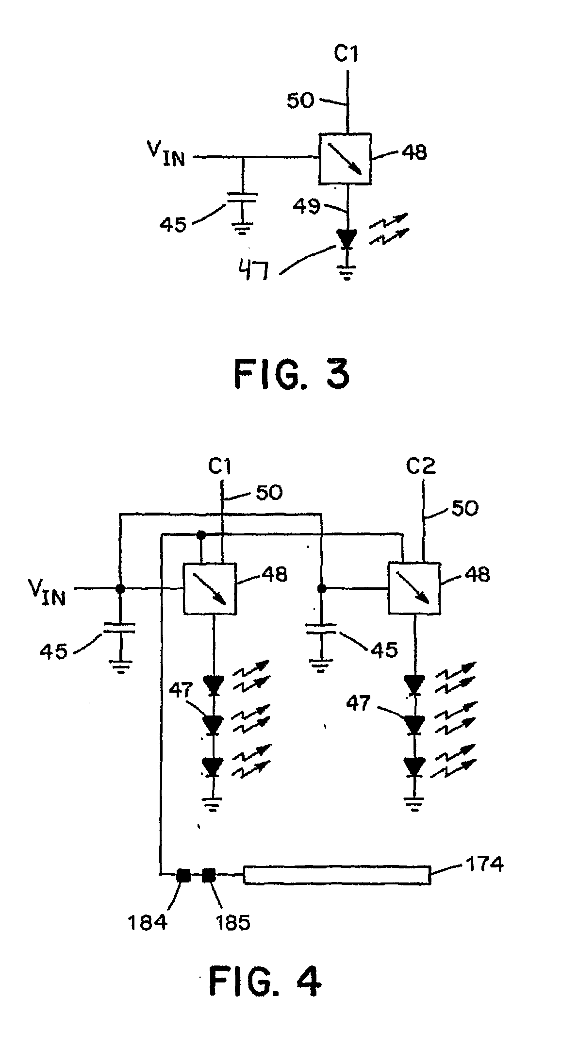
The invention relates to a skin tanning chamber, the improvement comprising at least one light emitting diode emitting a UVA light, such as a UVA LED that emits essentially only UVA. Additionally, multiple LEDs of varying types with various characteristic wavelengths are controlled independently to produce an arbitrary light pattern in an arbitrary sequence over time. The chamber can be rigid or flexible. It can be a bed, booth or incorporated into a flexible form, such as a garment or cloth. In one embodiment, the chamber further comprises at least one LED emitting a UVC light, whereby the UVC light sanitizes the chamber surface. Preferably the LED emitting the UVA light is under independent control from the LED emitting UVC light.

Description

CROSS-REFERENCE TO RELATED APPLICATIONS [0001] The present application claims benefit of U.S. Provisional Patent Application Ser. No. 60 / 552,018, filed Mar. 9, 2004; PCT Patent Application Number PCT / US2004 / 014527, filed May 24, 2004; PCT Patent Application Number PCT / US2004 / 016299, filed May 24, 2004, which are incorporated by reference in their entirety.FIELD OF THE INVENTION [0002] The present invention is directed generally to phototherapy systems and specifically to systems for treating lupus and psoriasis, for whitening teeth and for inducing hair growth. BACKGROUND [0003] The most common method of skin tanning involves the process of exposing skin to ultra-violet light. Health research has shown that both the condition of under-exposure to ultra-violet light and the condition of over-exposure to ultra-violet light causes a variety of health problems. Health research has also shown that specific ranges of wavelengths of ultra-violet light are responsible for producing health b...

Claims


Application Information

Patent Timeline
Patent Type & Authority Applications(United States)
IPC IPC(8): A61N5/06
CPCA61C19/066A61N5/0614A61N5/0616A61N5/0617A61N2005/0629A61N2005/0652A61N2005/0653A61N2005/0661B82Y30/00B82Y5/00
Inventor FISET, PETER DEPEW
Owner LEDEEP
Learn More