
Negative Pressure Ventilation and Resuscitation System

Inactive Publication Date: 2007-11-29
THE GENERAL HOSPITAL CORP
View PDF12 Cites 7 Cited by
  • Summary
  • Abstract
  • Description
  • Claims
  • Application Information

AI Technical Summary

Benefits of technology

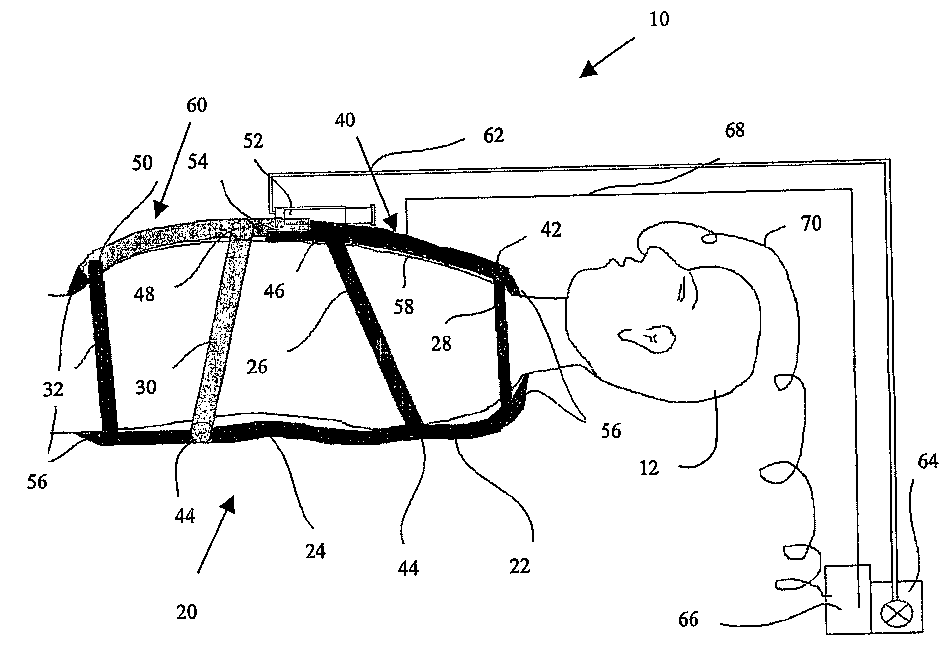
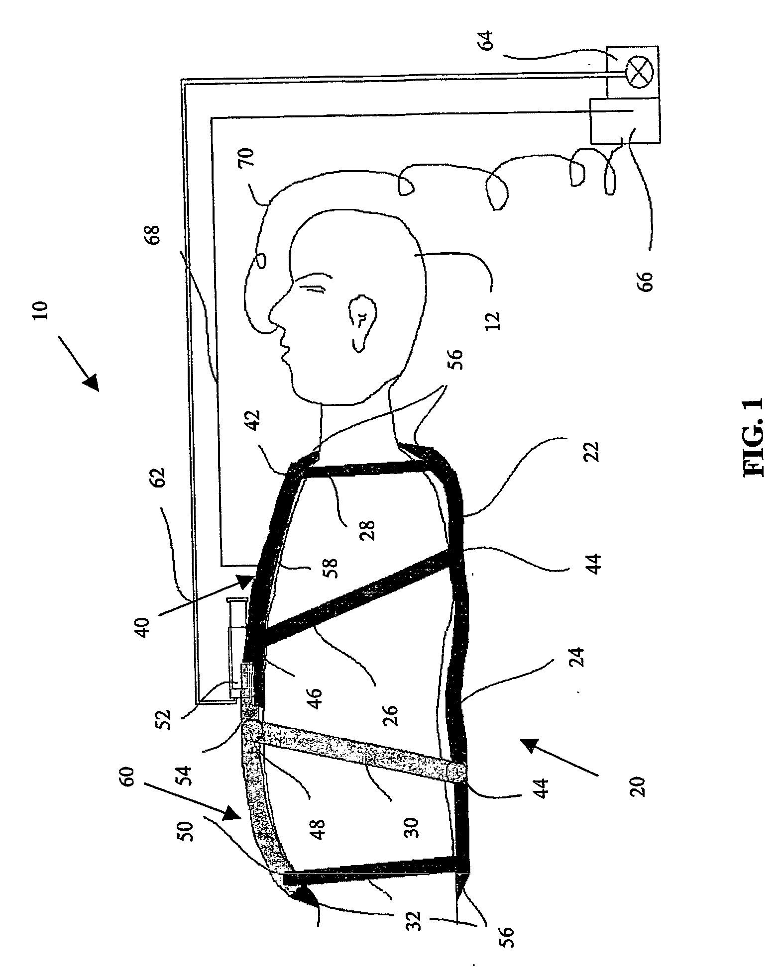
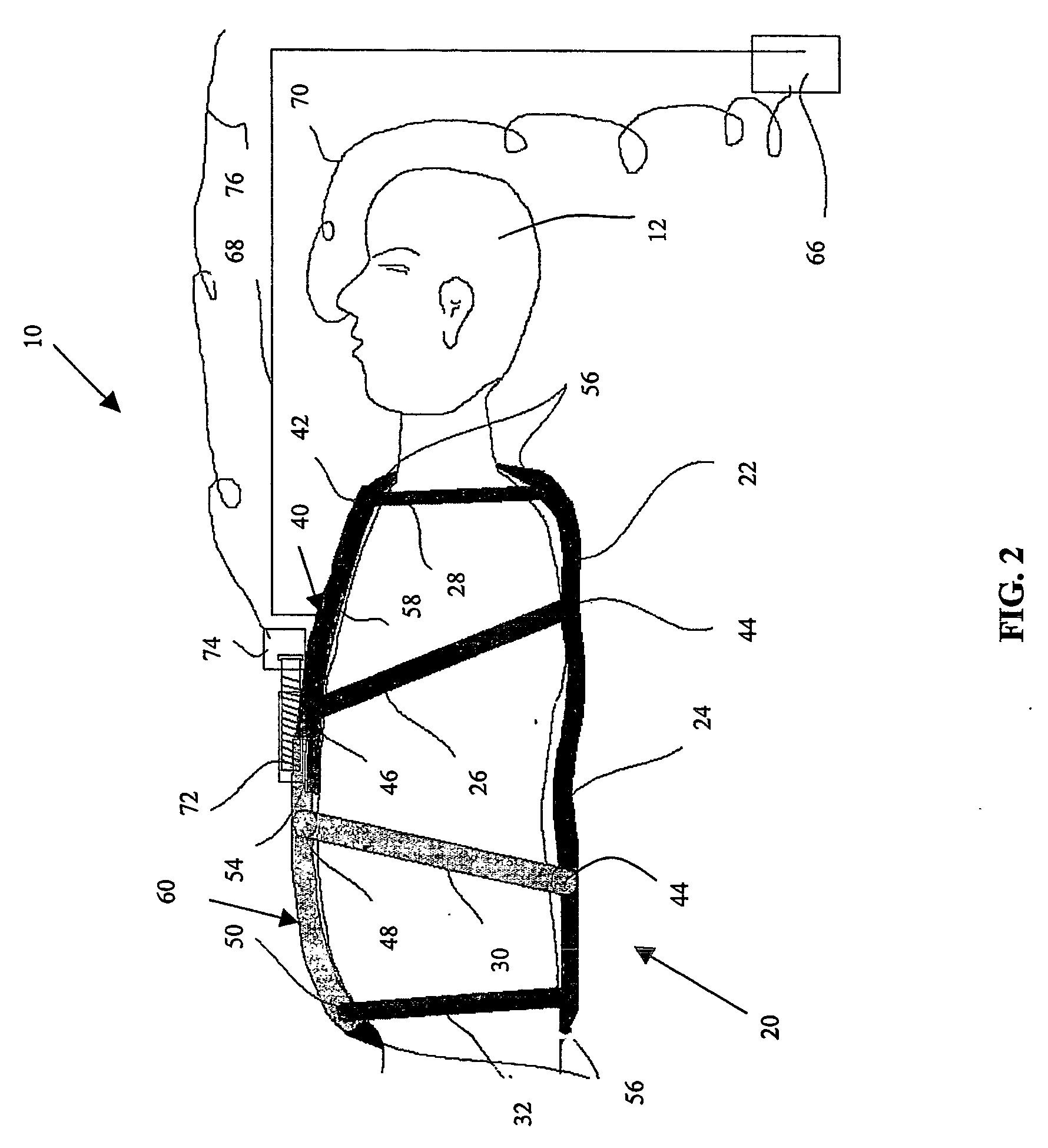
[0008] In operation, the artificial rib cage is moved by pulling up the anterior portion of the chest wall component of the artificial rib cage and at the same time pulling up the anterior portion of the abdominal component. As this happens, the anterior portion of the chest wall component and the abdominal component move away from the posterior portion of the chest wall component and abdominal component. This movement is achieved by changing the angle between the artificial spine and the artificial ribs of the artificial rib cage. Such movement allows the total size and the weight of the negative pressure ventilating system to be significantly simplified and reduced.
[0009] The present negative pressure ventilation system allows the generation of a transitory positive intra-thoracic pressure during the expiratory phase, increasing peak expiratory flow rate, initiating and / or facilitating a cough to help the patient clear airway secretions. An automatic feedback system can be incorporated into the ventilator to allow individual adjustment of the tidal volume, respiratory rate, and inspiratory: expiratory ratio (I:E ratio), allowing synchronization with the patient's spontaneous breathing. In addition, measured end tidal CO2 can be used to automatically adjust the tidal volume, respiratory rate or both.
[0010] The system can also provide more efficient cardiopulmonary compression. When a patient's blood circulation is inadequate, for example during cardiac arrest, a very important component of the resuscitation process is chest compression. Pressing and relieving the chest wall creates alternative positive and negative intra-thoracic pressure which, in turn with cardiac valve action, translates into an increased and then decreased intra-ventricular pressure to generate a forward blood flow. However, when the chest is pressed, the amplitude of the intra-thoracic pressure elevation is reduced by downward displacement of the diaphragm. When the pressure applied to the chest is removed, the re-coiling force stored in the chest wall during compression creates a negative intra-thoracic pressure which facilitates venous blood return and re-filling of the atria and ventricles. This process is made less efficient due to the upward movement of the diaphragm when the pressure applied to the chest wall is removed. This invention provides coordinated and opposed movement of the artificial rib cage and the abdominal components so that, during CPR, the amplitude of the positive and negative intra-thoracic pressure increases during a cycle of chest compression. Accordingly, the present system will make the resuscitation more efficient during CPR.

Problems solved by technology

This process is made less efficient due to the upward movement of the diaphragm when the pressure applied to the chest wall is removed.

Method used


Image

  • Negative Pressure Ventilation and Resuscitation System
  • Negative Pressure Ventilation and Resuscitation System
  • Negative Pressure Ventilation and Resuscitation System

Examples


Embodiment Construction

[0024] Certain exemplary embodiments will now be described to provide an overall understanding of the principles of the structure, function, manufacture, and use of the devices and methods disclosed herein. One or more examples of these embodiments are illustrated in the accompanying drawings. Those of ordinary skill in the art will understand that the devices and methods specifically described herein and illustrated in the accompanying drawings are non-limiting exemplary embodiments and that the scope of the present invention is defined solely by the claims. The features illustrated or described in connection with one exemplary embodiment may be combined with the features of other embodiments. Such modifications and variations are intended to be included within the scope of the present invention.

[0025] Turning now to the drawings of the present invention and particularly to FIG. 1, a negative pressure ventilation system 10, as applied on a patient 12, is shown. The system 10 inclu...


PUM


Abstract

A negative pressure ventilation system comprising a dynamically movable, multi-component artificial rib cage configured to fit snugly around the patient's own chest wall and abdomen is disclosed. The shape, dimensions and the dynamic movement of the artificial rib cage are designed to mimic those of the patient's own chest wall. The artificial rib cage includes an artificial spine to which are connected artificial ribs for forming an artificial chest wall including a sternum component. An abdominal component for placement on the patient's abdomen is connected to the chest wall component through a translating element which allows the abdominal component to move towards and away from the chest wall component. The chest wall and abdominal components cooperatively interact to allow the ventilator to move both the chest wall and abdomen during inspiration and expiration, mimicking the patient's own natural breathing pattern.

Description

FIELD OF THE INVENTION [0001] The present invention relates to respiratory assist devices, and more particularly to a ventilator system for assisting breathing in patients experiencing respiratory distress or respiratory failure. Even more specifically, the present invention relates to a negative pressure ventilator system with an artificial rib cage that can be driven to mimic the patient's own natural breathing pattern. BACKGROUND OF THE INVENTION [0002] Patients experiencing respiratory failure often require assisted ventilation from external devices or systems to facilitate ventilation (i.e., exchange of respiratory gases) and lung expansion and thereby prevent lung collapse. One known manner for facilitating breathing in these patients is to intermittently apply negative pressure around the chest wall, creating a negative pressure in the lungs and generating inward flow of air and / or other respiratory gases into the lungs. The energy stored in the lungs and the chest wall durin...

Claims


Application Information

Patent Timeline
IPC IPC(8): A61H31/00A61H31/02A61M
CPCA61H2230/40A61H31/02
Inventor JIANG, YANDONGKACMAREK, ROBERT M.ZAPOL, WARREN M.
Owner THE GENERAL HOSPITAL CORP
Learn More