
Biometric signatures and identification through the use of projective invariants

a biometric signature and projective invariant technology, applied in the field of biometric signatures and identification, can solve the problems of increasing intrusion into individual privacy, affecting the accuracy of biometric signatures, and often the need of pegs

Inactive Publication Date: 2007-11-29
UNIV OF COLORADO THE REGENTS OF
View PDF35 Cites 39 Cited by
  • Summary
  • Abstract
  • Description
  • Claims
  • Application Information

AI Technical Summary

Problems solved by technology

However, it suffers from extracting some small unique features from the fingerprints of elderly people as well as manual laborers whose fingerprints are worn out.
In addition, since fingerprint identification has been widely employed by law enforcement agencies, it becomes intrusive to individual's privacy.
Furthermore, fingerprints acquisition generally require contact further increasing its intrusiveness.
A major limitation of the prior art is the need for contact, and often the need of pegs.
This introduced several problems.
First, pegs can deform the shape of the hand.
Second, the dependence on alignment means improper placement of a hand can still happen due to the relatively complicated instruction, which can reduce the reliability of the system.
Finally, the prior art requires contact, which can be objectionable as it requiring users to place hands where many strangers just put their hands.
A key issue when considering projective invariants for biometrics is the actual feature points used to derive the invariant.
Thus the features themselves, the points on the occluding contour, are not viewpoint invariant and hence not suitable for use in defining projective invariants.

Method used


Image

  • Biometric signatures and identification through the use of projective invariants
  • Biometric signatures and identification through the use of projective invariants
  • Biometric signatures and identification through the use of projective invariants

Examples


Embodiment Construction

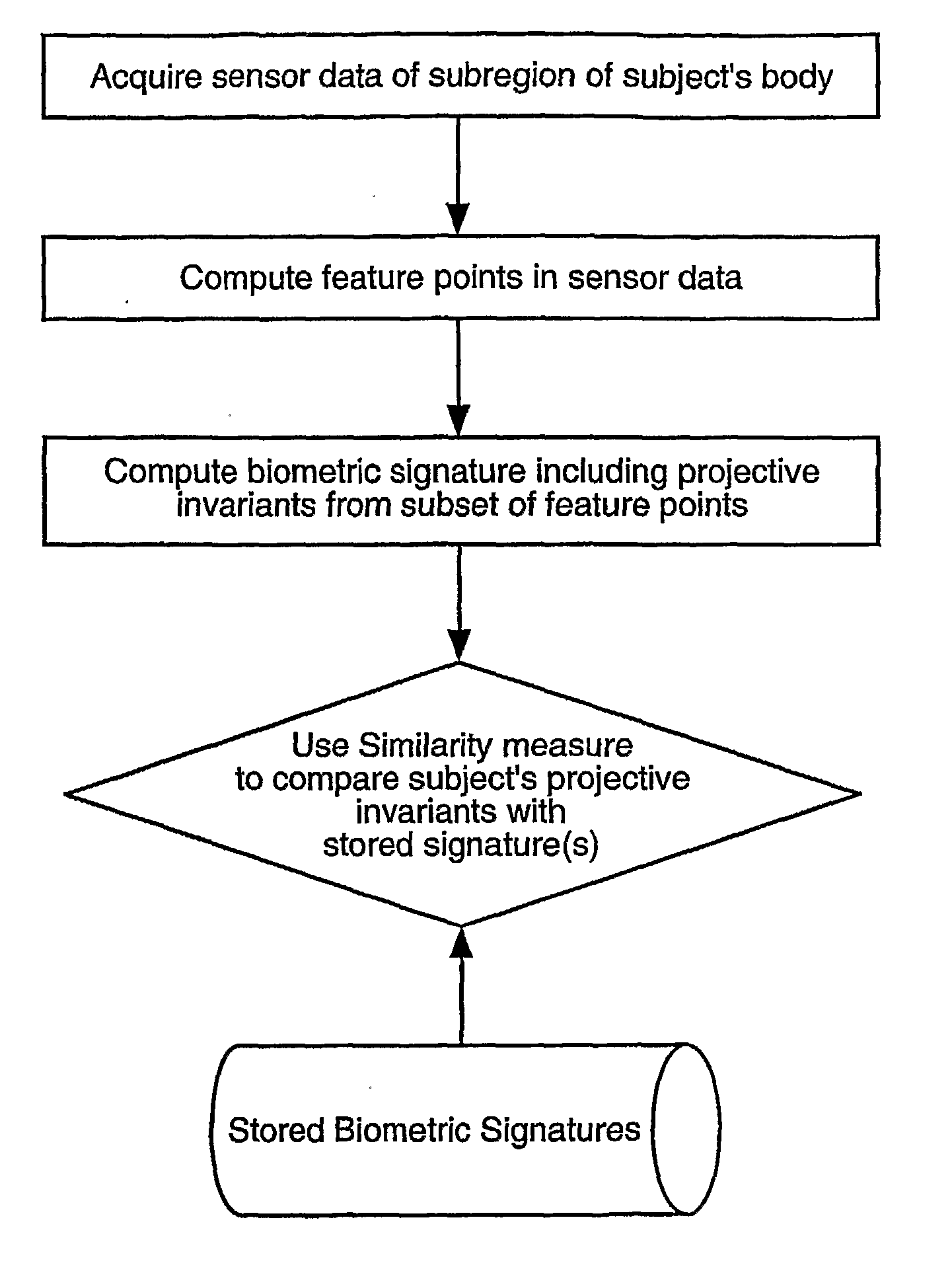
[0040] Techniques, systems and methods for obtaining biometric signatures and identification are described. Broadly stated, embodiments of the present invention utilize specified geometric principles to provide means for accurate biometric identification using projective invariant or projective quasi-invariant features of a subregion of the human body.

[0041] In the following description, for the purposes of explanation, numerous specific details are set forth in order to provide a thorough understanding of embodiments of the present invention. It will be apparent, however, to one skilled in the art that embodiments of the present invention may be practiced without some of these specific details. In other instances, well-known structures and devices are shown in block diagram form.

[0042] Certain elements of the embodiments of the present invention include various steps, which will be described below. The steps may be performed by hardware components or may be embodied in machine-ex...


PUM


Abstract

Techniques, systems and methods for obtaining biometric signatures and identification are described. Broadly stated, embodiments of the present invention utilize specified geometric principles t provide means for accurate biometric identification using projective invariant features of a subregion of the human body. The present invention provides a means for computing biometric signatures and identification that are projective invariant and hence are not impacted by the viewing angle of the subregion of the human body containing the biometric data. This novel invention removes the restriction, often implicit in the previous work, of the imaging or sensing system being in a fixed repeatable (and generally orthogonal) viewing position. This invention can be applied across a wide range of biometrics, although it is most easily applicable to features that are approximately co-planar. A plurality of such projective invariant features can be used to define a biometric signature to either verify an individual's identity, or recognize an individual from a database of already known persons.

Description

STATEMENT REGARDING FEDERALLY SPONSORED RESEARCH OR DEVELOPMENT [0001] The work of the inventors was supported in part by Air Force Research Lab under agreement number F49620-03-1-0207 through Network Information and Space Security Center (NISSC), U. Colorado at Colorado Springs. It was also funded in part by DARPA HID program under contract number N00014-00-1-0929, and by the Colorado Institute for Technology Transfer and ImplementationCOPYRIGHT NOTICE [0002] Contained herein is material that is subject to copyright protection. The copyright owner has no objection to the facsimile reproduction of the patent disclosure by any person as it appears in the Patent and Trademark Office patent files or records, but otherwise reserves all rights to the copyright whatsoever. BACKGROUND [0003] 1. Field [0004] Embodiments of the present invention generally relate to biometric signatures and identification. More specifically, embodiments of the present invention describe a system and method fo...

Claims


Application Information

Patent Timeline
IPC IPC(8): G06F19/00
CPCG06K9/00375G06V40/107
Inventor BOULT, TERRANCE EDWARDZHENG, GANGWANG, CHIA-JIU
Owner UNIV OF COLORADO THE REGENTS OF
Learn More