
Tag communication device, tag moving direction detecting system and tag moving direction detecting method

Active Publication Date: 2007-11-29
ORMON CORP
View PDF7 Cites 37 Cited by
  • Summary
  • Abstract
  • Description
  • Claims
  • Application Information

AI Technical Summary

Benefits of technology

[0007] The present invention is made to solve the above problem points, and its object is to provide a tag communication device, a tag moving direction detecting system and a tag moving direction detecting method able to detect the moving direction of the moving body attaching the RFID tag thereto by simple processing, and able to easily detect the moving direction even when its moving speed is increased.
[0029] The above plural antenna elements may be also constructed by a patch antenna, and are further two-dimensionally arrayed. The above scan antenna may be also set so as to perform two-dimensional scan with respect to the moving path of the above moving body. If the plural antennas are constructed from the patch antenna, the scan antenna can be thinly manufactured, and manufacture cost can be lowly restrained so that it is suitable. Further, if the plural antennas are two-dimensionally arrayed, e.g., if the plural antenna elements are arrayed in a circular shape, a matrix shape, etc. on the same plane, the scan can be performed so as to draw a circle. Accordingly, the moving direction of the moving body can be two-dimensionally detected. Namely, when the moving body is moved on the XY plane, a movement to the X-direction and a movement to the Y-direction can be simultaneously detected.
[0036] As explained above, in accordance with the present invention, the beam of the radio wave transmitted by the scan antenna toward the space on the moving path of the moving body with the RFID tag is scanned. Plural sets of the scan angle and the time passage information are generated, and the moving direction is detected by using generated data. Thus, the moving direction of the moving body sticking the RFID tag thereto can be simply detected without requiring complicated scan control of the scan antenna as in the technique disclosed in JP-A-2005-345198. Further, when the moving body is conveyed at high speed, the reading number of the RFID tag can be increased by merely adjusting the speed of scan in accordance with its conveying speed. As a result, an operation effect in which accuracy of detection of the moving direction can be easily improved, etc. are obtained.

Problems solved by technology

However, no detection can be performed for a conveying direction of this baggage.
Therefore, a problem exists in that it is impossible to automatically detect whether it is warehousing or forwarding.
However, in accordance with the technique of this JP-A-2005-345198, if the number of RFID tags 200 is increased, its processing becomes complicated and it becomes difficult to pursue the movement of each RFID tag 200.
Otherwise, a problem exists in that it takes much time until detection even when this position is detected.

Method used


Image

  • Tag communication device, tag moving direction detecting system and tag moving direction detecting method
  • Tag communication device, tag moving direction detecting system and tag moving direction detecting method
  • Tag communication device, tag moving direction detecting system and tag moving direction detecting method

Examples


Embodiment Construction

[0060] A best mode for embodying the present invention will next be explained in detail with reference to the accompanying drawings.

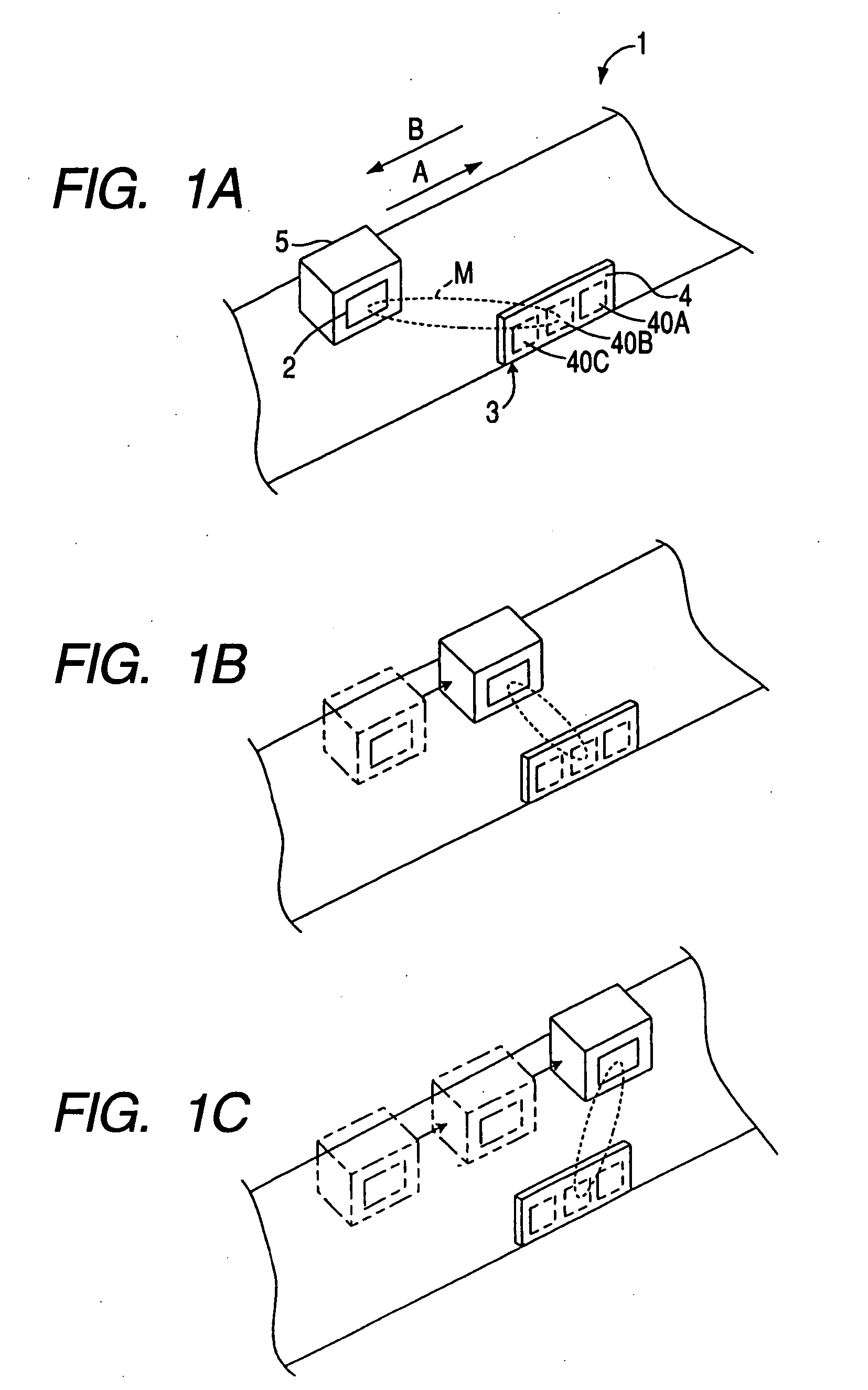
[0061]FIGS. 1A to 1C are explanatory views showing the summary of a first embodiment mode of a RFID communication system applying the present invention thereto. The RFID communication system 1 of this figure manages warehousing and forwarding of many pieces of baggage 5 (moving body) conveyed by a belt conveyer 6. With respect to the RFID tag 2 respectively attached to the baggage 5, a reader-writer 3 reads and writes data by performing wireless communication.

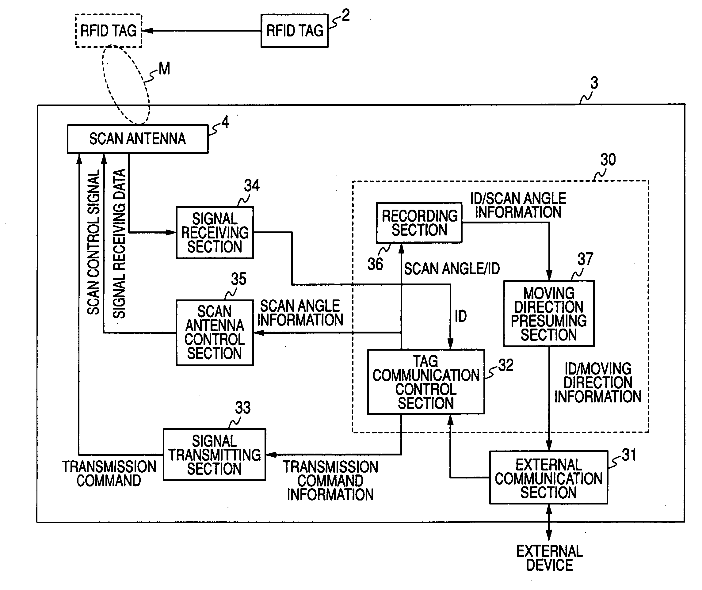
[0062] The summary of this embodiment mode will be explained. In FIGS. 1A to 1C, the reader-writer 3 has a scan antenna 4 although simplified and described. The scan antenna 4 has three antenna elements 40A, 40B, 40C arrayed in a straight line shape along the belt conveyer 6, and repeatedly scans the direction of a beam M of a radio wave transmitted to the exterior as shown in FIGS. 1A to 1C. On ...


PUM


Abstract

The invention provides a tag communication device, a tag moving direction detecting system and a tag moving direction detecting method able to detect the moving direction of a moving body attaching a RFID tag thereto by simple processing, and able to easily detect the moving direction even when its moving speed is increased. A scan antenna scans a beam of a transmitted radio wave toward a belt conveyer for conveying baggage with a RFID tag. ID is read from the RFID tag, and reading NO. and a scan angle are related and recorded to a measuring data table, and plot data are generated. These plot data are plotted in an XY coordinate system, and a plot graph is generated. Further, a linear approximate straight line is calculated from this plot graph, and a moving direction of the baggage is detected from an inclination value of the linear approximate straight line.

Description

BACKGROUND OF THE INVENTION [0001] 1. Field of the Invention [0002] The present invention relates to a tag communication device, a tag moving direction detecting system and a tag moving direction detecting method able to detect a moving direction of a moving body attaching a RFID tag thereto. [0003] 2. Background Art [0004] A technique for sticking a RFID (Ratio Frequency Identification) tag to baggage and managing the baggage by performing wireless communication of this RFID tag and a reader-writer is recently used. In accordance with this technique, for example, data of ID (Identification), etc. can be automatically read from the RFID tag attached to the baggage conveyed by a belt conveyer, etc. Accordingly, an commodity distribution operation is efficiently intentionally performed. However, no detection can be performed for a conveying direction of this baggage. Therefore, a problem exists in that it is impossible to automatically detect whether it is warehousing or forwarding. [...

Claims


Application Information

Patent Timeline
IPC IPC(8): G08B13/14H04Q5/22
CPCG01S13/58H04W88/02G01S13/74
Inventor KOEZUKA, YAHIROIIDA, KISHO
Owner ORMON CORP
Learn More