Radio frequency identification tag and antenna for radio frequency identification tag
a radio frequency identification and antenna technology, applied in the direction of resonant antennas, instruments, burglar alarm mechanical actuation, etc., can solve the problem of not being able to speedily manufacture such a complex antenna configuration with high precision, and achieve the effect of shortening the communication distance small thickness of the radio frequency identification tag
- Summary
- Abstract
- Description
- Claims
- Application Information
AI Technical Summary
Benefits of technology
Problems solved by technology
Method used
Image
Examples
first embodiment
of the Present Invention
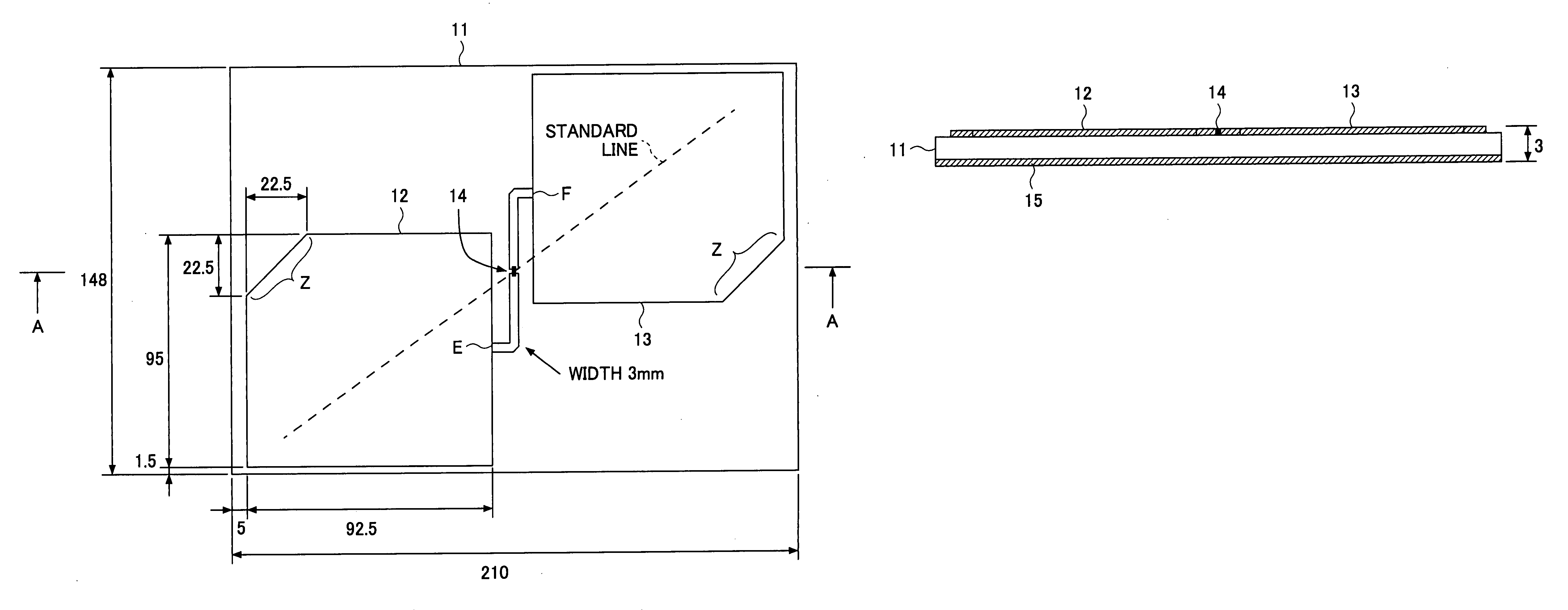
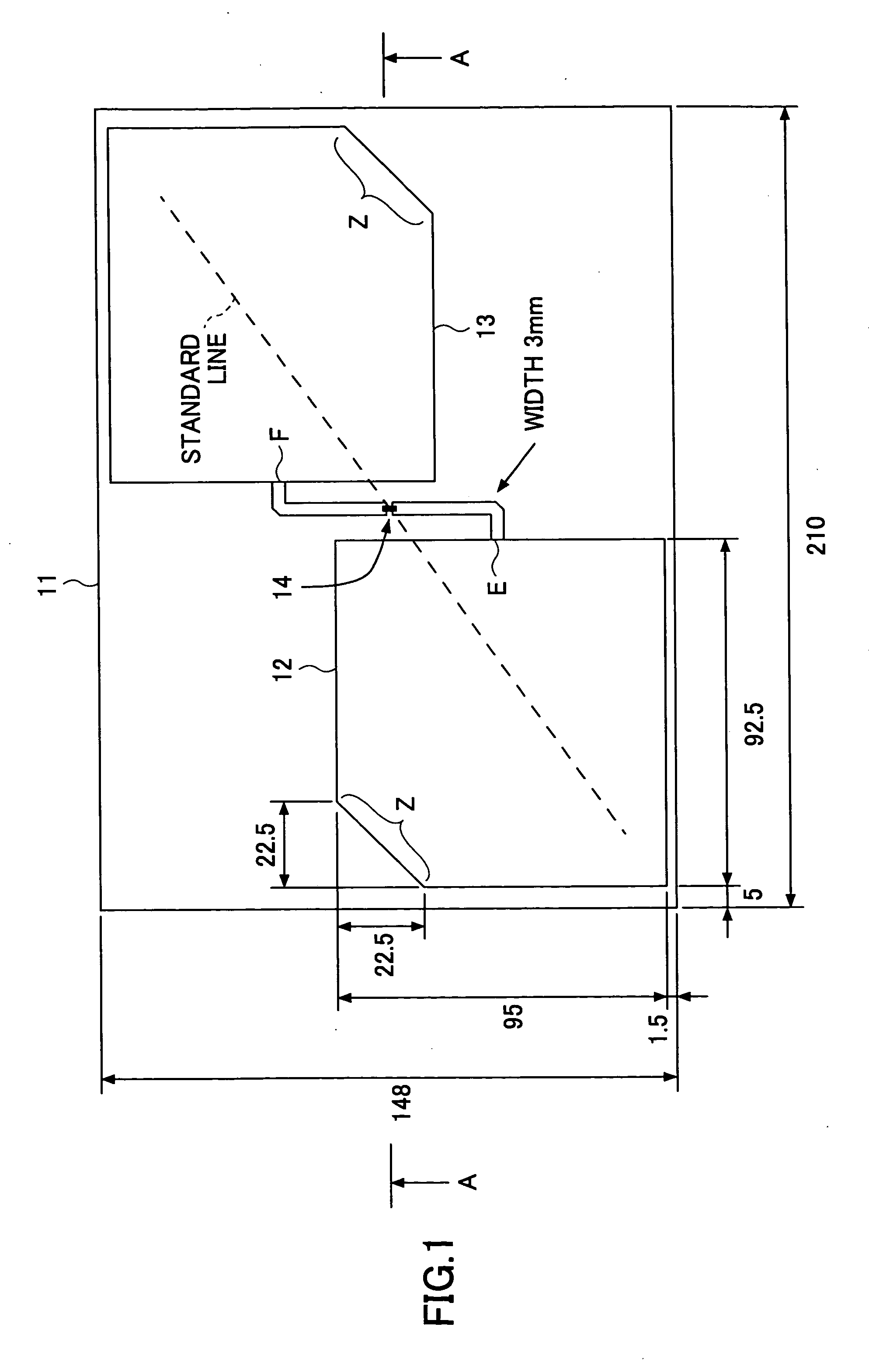
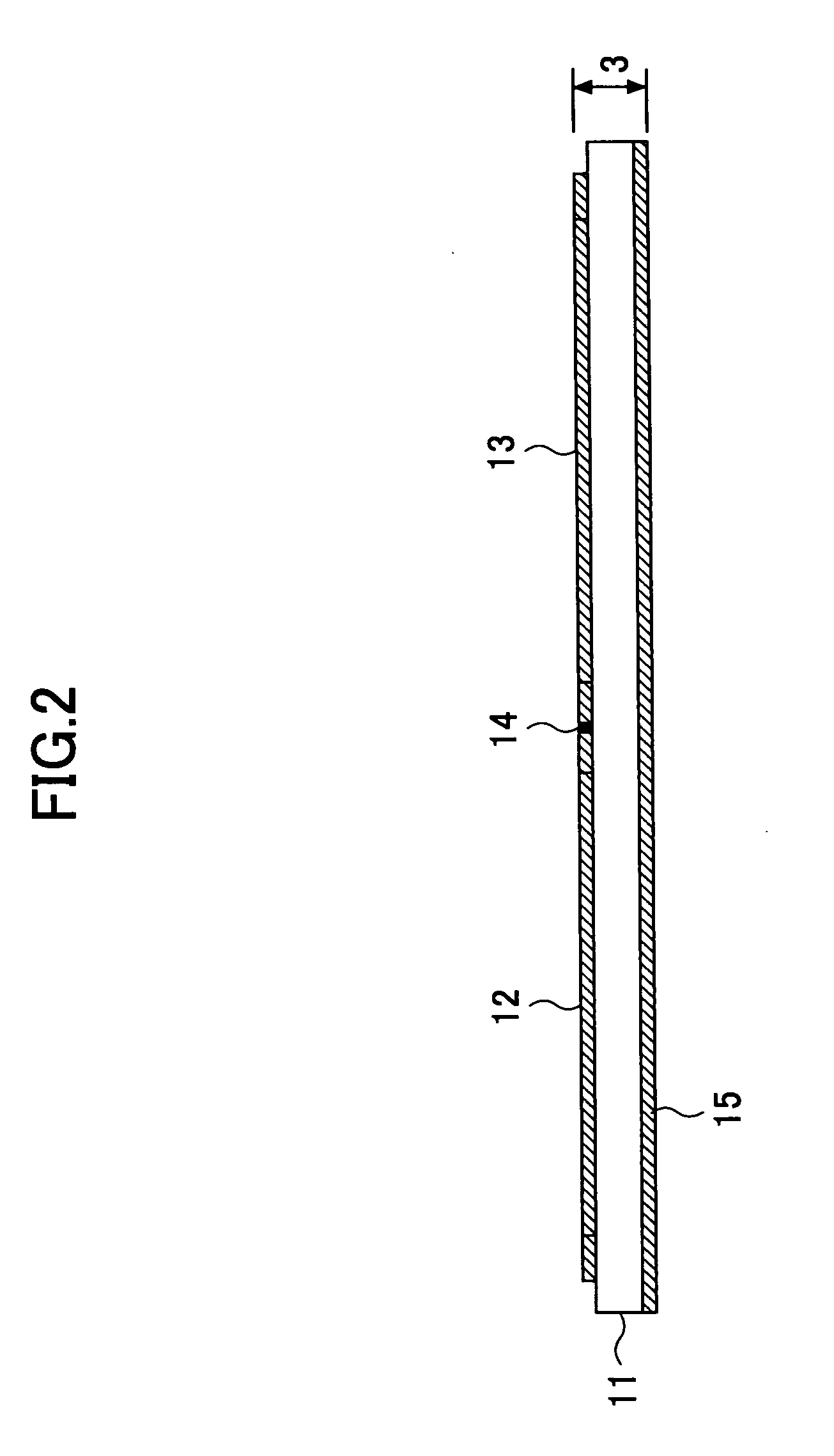
[0049]FIG. 1 is a plan view of a radio frequency identification tag of a first embodiment of the present invention. FIG. 2 is a cross-sectional view taken along a line A-A of the radio frequency identification tag shown in FIG. 1.
[0050]Referring to FIG. 1 and FIG. 2, a radio frequency identification tag of a first embodiment of the present invention includes a dielectric board 11, a pair of conductive plates 12 and 13 provided on a surface of the dielectric board 11, a radio frequency identification tag integrated circuit (that may be called a tag LSI or tag IC) 14, and a ground conductive plate 15 provided on a rear surface of the dielectric board 11.
[0051]The radio frequency identification tag receives and transmits a signal of a Ultra-High Frequency (UHF) band via the pair of the conductive plates 12 and 13. A unit of measurement in FIG. 1 is “mm”. However, numerical values are just examples and various numerical values may be used in the scope of the pres...
second embodiment
of the Present Invention
[0070]In the meantime, the reader / writer device transmits a circularly polarized wave signal to the radio frequency identification tag so that electric power and an opportunity of response are given to the radio frequency identification tag.
[0071]The conventional radio frequency identification tag has, for simplification of the structure, an antenna for receiving and transmitting a linearly polarized wave signal.
[0072]If the reader / writer device also transmits the linearly polarized wave signal to the radio frequency identification tag, the amount of an electric power supplied to the radio frequency identification tag drastically depends on a positional relationship of the reader / writer device and the radio frequency identification tag. If a polarization plane of the reader / writer device and a polarization plane of the radio frequency identification tag cross each other, the radio frequency identification tag may not respond with a proper response signal to t...
third embodiment
of the Present Invention
[0090]In the above-discussed first and second embodiments of the present invention, the antenna having the pair of the conductive plates provided on the board in a symmetrical manner with respect to the tag LSI is used for the radio frequency identification tag accompanying a metal subject.
[0091]However, such an antenna may be used for a radio frequency identification tag accompanying a non-metal subject. In the third embodiment of the present invention, the antenna used for the radio frequency identification tag accompanying the non-metal subject is discussed.
[0092]FIG. 9 is a plan view showing a radio frequency identification tag of the third embodiment of the present invention.
[0093]Referring to FIG. 9, the radio frequency identification tag of the third embodiment of the present invention includes a dielectric board (not shown), a pair of conductive plates 82 and 83 provided on a surface of the dielectric board, and a tag LSI 84. In this embodiment, the g...
PUM
 Abstract
Description
Claims
Application Information
 - R&D
- Intellectual Property
- Life Sciences
- Materials
- Tech Scout
- Unparalleled Data Quality
- Higher Quality Content
- 60% Fewer Hallucinations
Browse by: Latest US Patents, China's latest patents, Technical Efficacy Thesaurus, Application Domain, Technology Topic, Popular Technical Reports.
© 2025 PatSnap. All rights reserved.Legal|Privacy policy|Modern Slavery Act Transparency Statement|Sitemap|About US| Contact US: help@patsnap.com


