
Two-bar linkage fast elevating apparatus for screen printing machine

a screen printing machine and fast technology, applied in the direction of printing, inking apparatus, coating, etc., can solve the problems of difficulty in positioning and removing objects, adverse effects on the productivity of the screen printing machine, and the failure of conventional screen printing machines to achieve fast and high-quality printing to satisfy the market demands, so as to improve yield and productivity, convenient and quick positioning of objects, and accurately inspecting printing quality

Inactive Publication Date: 2007-11-29
ATMA CHAMP ENTERPRISE
View PDF3 Cites 7 Cited by
  • Summary
  • Abstract
  • Description
  • Claims
  • Application Information

AI Technical Summary

Benefits of technology

[0006]A primary object of the present invention is to provide a two-bar linkage fast elevating apparatus for screen printing machine, so that the screen printing machine can perform high-speed and high-precision printing operation.
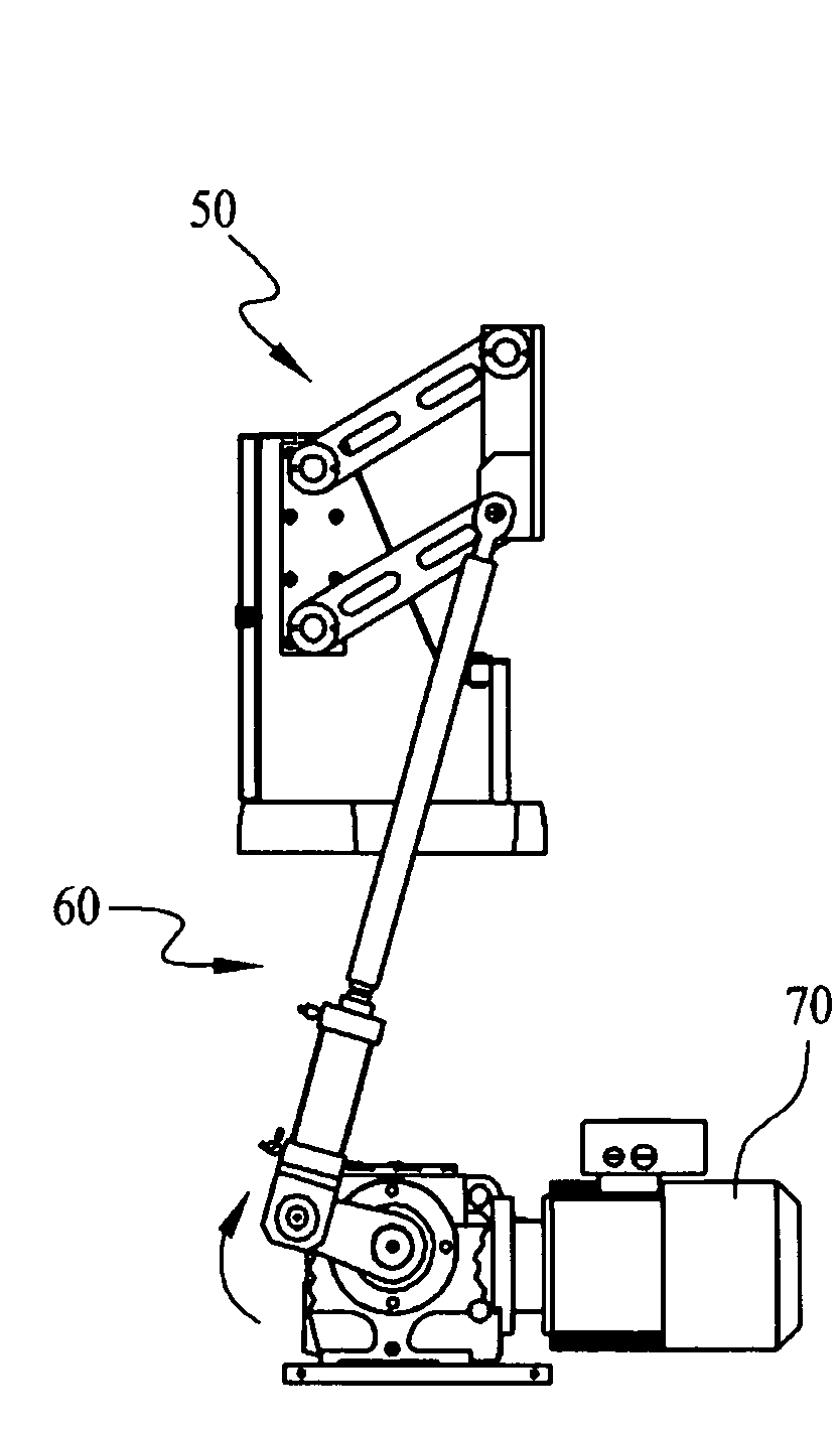
[0007]Another object of the present invention is to provide a two-bar linkage fast elevating apparatus consisting of a two-bar linkage system and an eccentric shaft driving system for use with a screen printing machine. The two-bar linkage system and the eccentric shaft driving system are connected to a transverse slide base of the screen printing machine, and are driven by a reduction motor mounted at a lower part of a platform of the machine to quickly lift and lower the transverse slide base.
[0008]A further object of the present invention is to provide a two-bar linkage fast elevating apparatus consisting of a two-bar linkage system and an eccentric shaft driving system for use with a screen printing machine. The two-bar linkage system and the eccentric shaft driving system are connected to a transverse slide base of the screen printing machine, and are driven by a reduction motor mounted at a lower part of a platform of the machine to quickly lift while rearward moves the transverse slide base, so that a space between the lifted screen and printing head held to a front side of the transverse slide base and the printing bed has increased height and depth to provide good vision for an operator to easily check the printing quality.
[0021]When the present invention is in use, the reduction motor operates at a high speed to drive the eccentric shaft driving system to together with the two-bar linkage system stably lift or lower the transverse slide base at a high speed. The reduction motor is designed to rotate cyclically to change the working position of the two-bar linkage fast elevating apparatus. When the eccentric shaft driving system is in the lowest or printing position, the printing head of the screen printing machine is moved transversely to scrape ink on the screen, and produces a downward pressure against the screen, causing the ink to penetrate through the screen to an object to be printed. When the printing is completed, the reduction motor lifts while rearward moves the transverse slide base of the screen printing machine to the highest or standby position, enabling the operator to more conveniently and quickly position the object to be printed, check the printing quality, or remove the printed object from the printing bed. The enlarged space between the lifted screen and the printing bed of the screen printing machine provides good vision for the operator to accurately inspect the printing quality, so as to ensure increased good yield and productivity from the printing operation.

Problems solved by technology

Due to the limited space, it is relatively difficult for the operator to position and remove the objects to be printed or having been printed, and the productivity of the screen printing machine is adversely affected.
Since the elevating and the transverse slide base in the conventional screen printing machines are pneumatically driven and could not be quickly actuated under control, the conventional screen printing machines fail to achieve fast and high-quality printing to satisfy the market demands.

Method used


Image

  • Two-bar linkage fast elevating apparatus for screen printing machine
  • Two-bar linkage fast elevating apparatus for screen printing machine
  • Two-bar linkage fast elevating apparatus for screen printing machine

Examples


Embodiment Construction

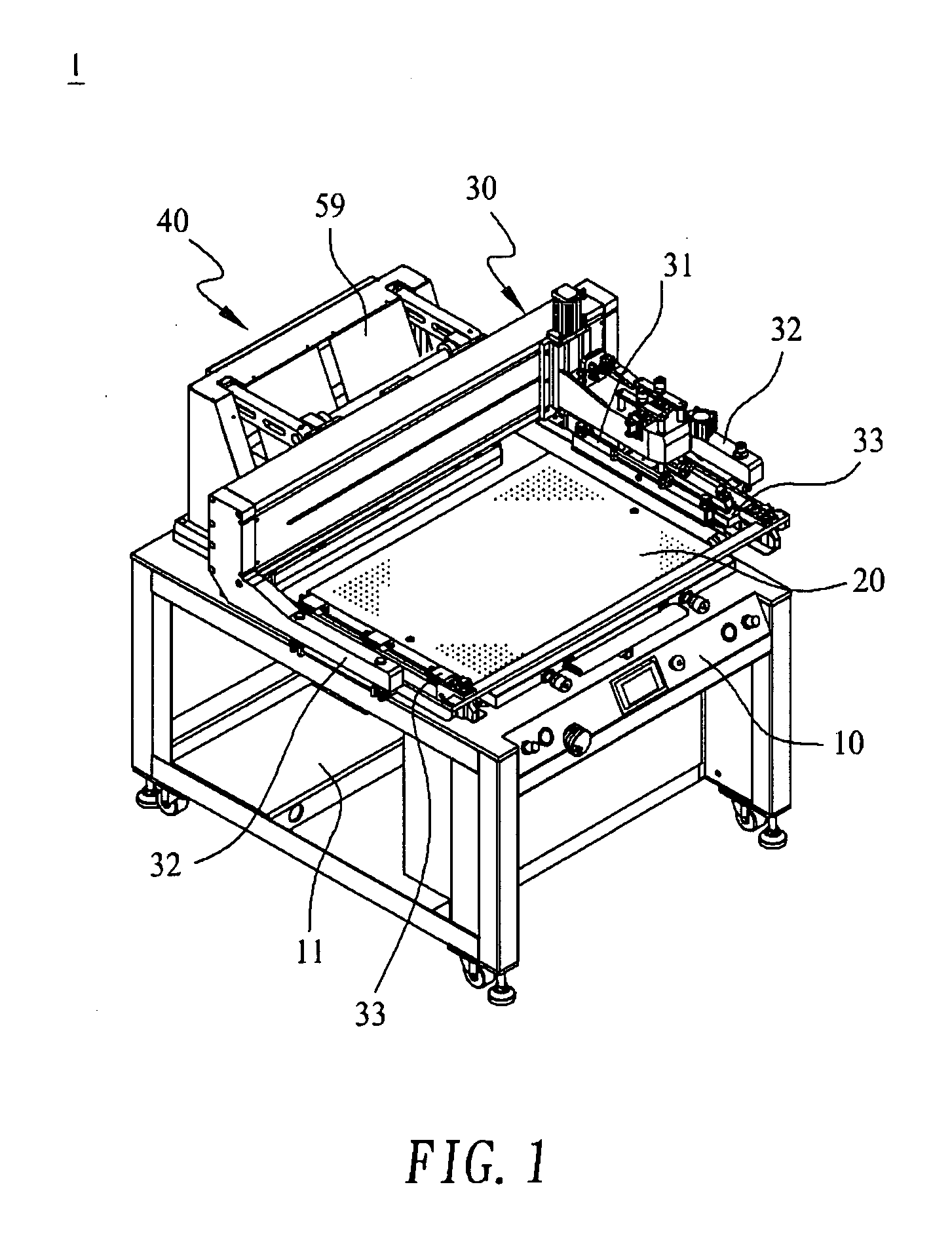
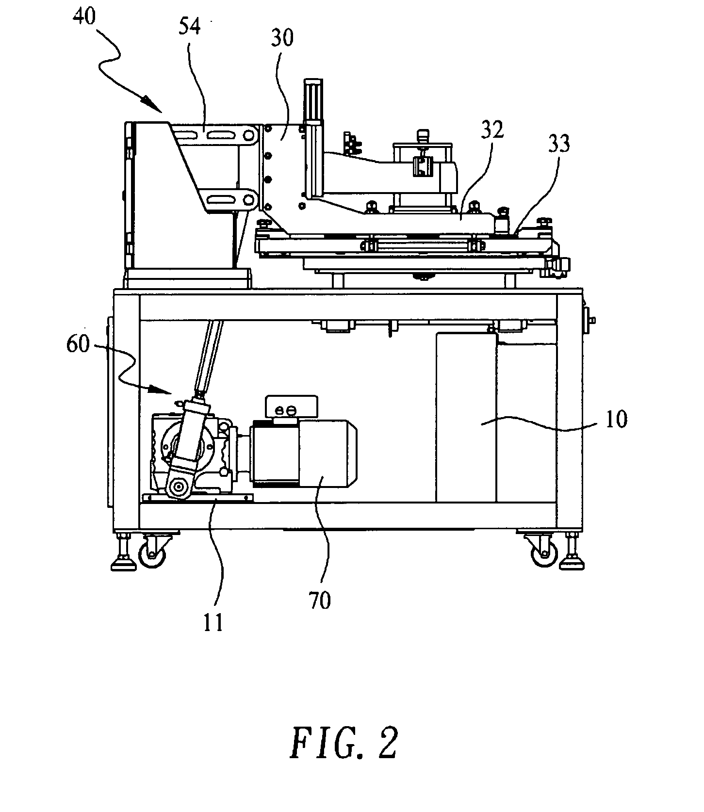
[0032]Please refer to FIGS. 1 and 2 that are assembled perspective and side views, respectively, showing a screen printing machine 1 equipped with a two-bar linkage fast elevating apparatus 40 according to a preferred embodiment of the present invention. The illustrated screen printing machine 1 is a cantilever-type screen printing machine basically including a platform 10, a printing bed 20, a transverse slider 30, the two-bar linkage fast elevating apparatus 40, and other related mechanisms. The transverse slide base 30 has a cantilevered printing head 31 forward extended therefrom to leftward and rightward slide along the transverse slide base 30, and is provided at two lateral ends thereof with two forward extended cantilevered arms 32. Each of the two cantilevered arms 32 is provided at a lower side with a clamping support 33 for holding a screen frame between the two cantilevered arms 32. The two-bar linkage fast elevating apparatus 40 is connected to a rear side of the transv...


PUM


Abstract

A two-bar linkage fast elevating apparatus for screen printing machine includes a two-bar linkage system and an eccentric shaft driving system connected to a rear side of a transverse slide base of the screen printing machine. A reduction motor is connected to a lower end of the eccentric shaft driving system to cyclically lift and lower the eccentric shaft driving system. When the eccentric shaft driving system is lifted to elevate the transverse slide base, the two-bar linkage system synchronously moves the transverse slide base backward, so that a heightened and deepened space giving good vision is provided between a printing bed and a lifted screen of the screen printing machine for an operator to safely, conveniently, and accurately check the printing quality.

Description

FIELD OF THE INVENTION[0001]The present invention relates to a two-bar linkage fast elevating apparatus, and more particularly to a fast elevating apparatus that employs a two-bar linkage system and an eccentric shaft driving system to rearward lift a printing structure of a screen printing machine to produce a sufficient space with good vision above a printing bed of the machine, so that an operator may safely and accurately check the quality of printed objects.BACKGROUND OF THE INVENTION[0002]A cantilever-type screen printing machine is one of many important printing machines and is particularly suitable for precision printing on circuit boards. This type of screen printing machine typically includes a platform having an upper surface defining a printing bed, an elevating slide base provided to one lateral side of the platform, a transverse slide base mounted on the elevating slide base to move leftward and rightward, a cantilevered printing head forward extended from the transver...

Claims


Application Information

Patent Timeline
Patent Type & Authority Applications(United States)
IPC IPC(8): B05C17/08B41L13/00
CPCB41F15/0881H05K3/1216B41F33/04B41F15/36
Inventor CHEN, TUNG CHIN
Owner ATMA CHAMP ENTERPRISE
Learn More