
Torque Rod Structure

a technology of torque rods and rod components, applied in the direction of connecting rod bearings, jet propulsion mounting, transportation and packaging, etc., can solve the problems of not being able to increase the twisting stiffness, not being able to take into account other requirements, and not being able to meet the demands of bending and twisting stiffness in recent years, so as to improve the rod portion, increase the bending and twisting stiffness, and improve the effect of rod portion

Inactive Publication Date: 2007-11-29
HONDA MOTOR CO LTD
View PDF4 Cites 32 Cited by
  • Summary
  • Abstract
  • Description
  • Claims
  • Application Information

AI Technical Summary

Benefits of technology

The present invention relates to an improved torque rod design for vehicles that addresses the requirements of bending and twisting stiffness. The invention provides a torque rod with a hollow cross-sectional shape or plural void portions in the rod portion, which increases the stiffness of bending and twisting. The invention also includes a structure with plural hole portions forming cross-shaped ribs to further improve the twisting and bending stiffness of the rod portion. Overall, the invention improves the performance of torque rods in terms of bending and twisting stiffness.

Problems solved by technology

However, for such a torque rod 10, whilst this can satisfy the requirements in terms of raising the compression strength and tensile strength, it is not a shape which takes into account other requirements.
For example, the current situation is that the demands in recent years for bending stiffness and twisting stiffness are not adequately provided for.
However, against bending and twisting, the secondary moment and section modulus is lowered, and, for example, it is pointed out that the twisting stiffness cannot be increased.

Method used


Image

  • Torque Rod Structure
  • Torque Rod Structure
  • Torque Rod Structure

Examples


example 1

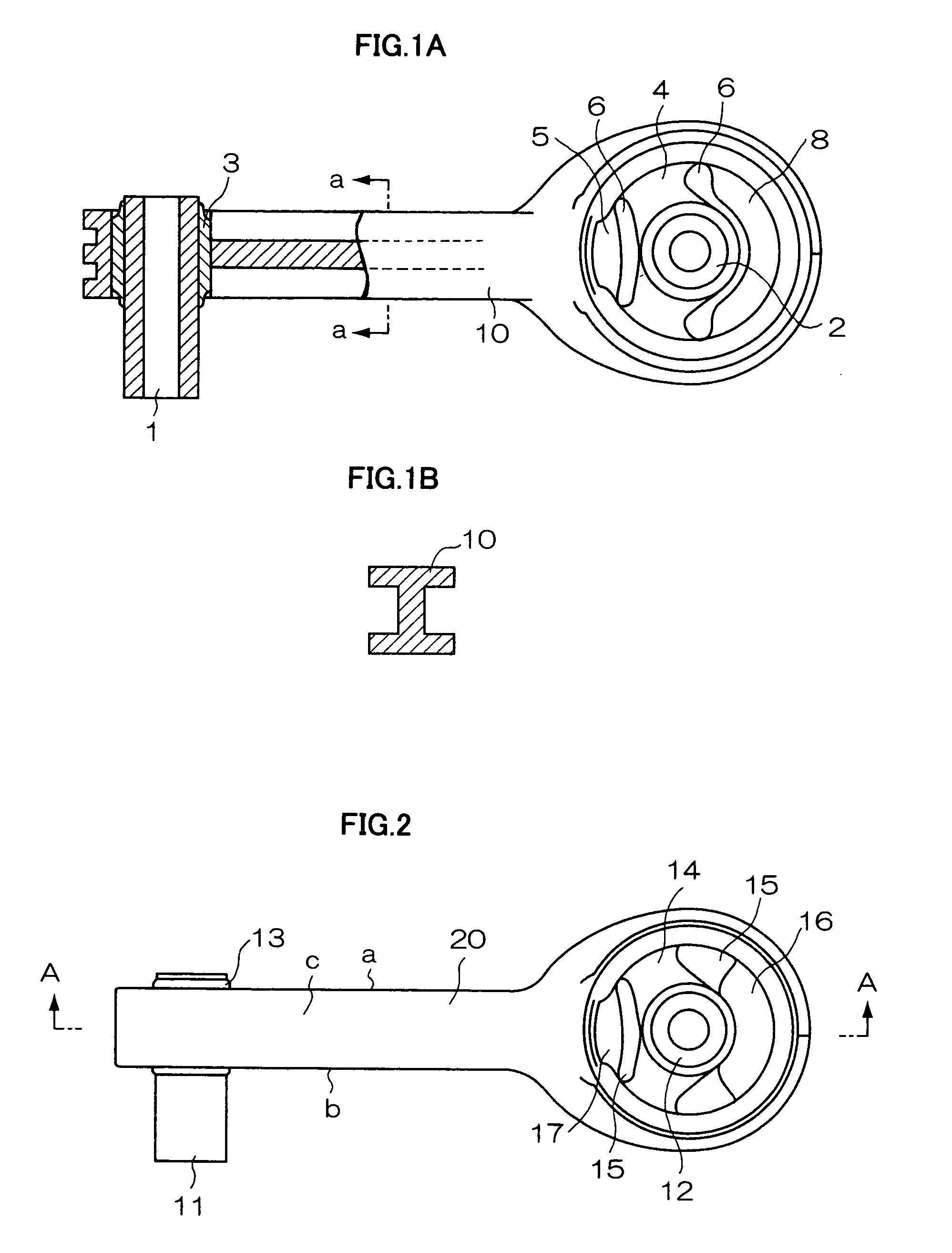
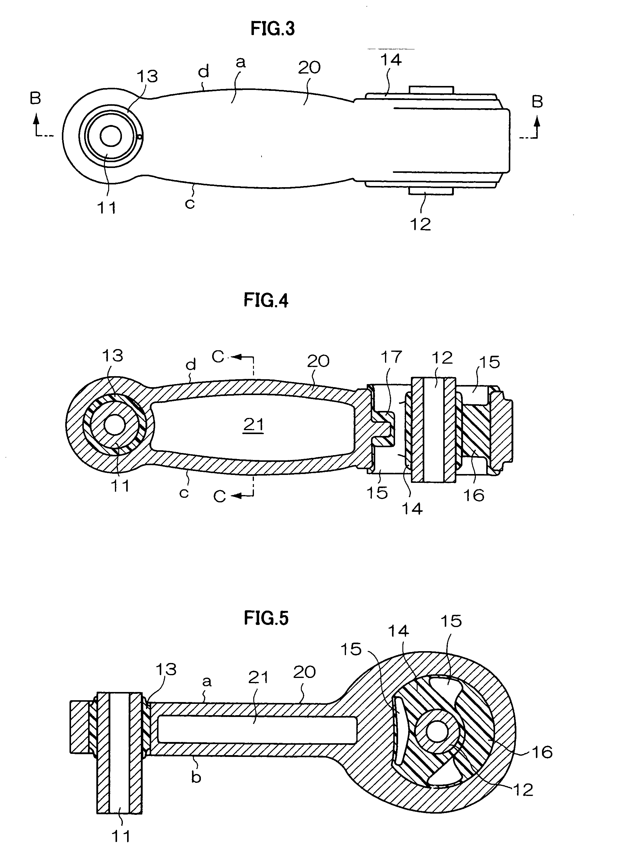
[0034] FIGS. 2 to 6 are examples of the first invention, FIG. 2 is a front view, FIG. 3 is a side view, FIG. 4 is a cross-section on the line A-A, FIG. 5 is a cross-section on the line B-B, FIG. 6 is a cross-section on the line C-C. The numerals 11,12 are a pair of internal cylinders disposed at 90 degrees to each other, 13 is a rubber bush which covers the internal cylinder 11, 14 is a rubber bush which covers the internal cylinder 12, 15 is a hollow portion formed on the inner and outer sides of the internal cylinder 12, and stoppers 16,17 are provided sandwiched by the hollow portion 15. The torque rod 20 made of a polyamide resin is connected thereto.

[0035] Because the internal cylinder 11 is surrounded by rubber bush 13 it does not move, but the other internal cylinder 12 is comparatively free to move because of the hollow portion 15, and in this case, the movement thereof becomes regulated by impacting with the stoppers 16, 17.

[0036] The torque rod 20 is approximately rectan...

example 2

[0038] Now, in cases where the hollow portion 21 cannot be made by casting as with aluminum alloy, whilst it is not illustrated, it goes without saying that the cross-section on C-C can be preliminary made as a “U” section, and then the hollow portion 21 can be formed by using a flat plate as a cap for the remaining face.

example 3

[0039] FIGS. 7 to 11 are examples of the second invention, FIG. 7 is a front view, FIG. 8 is a side view, FIG. 9 is a cross-section on the line D-D, FIG. 10 is a cross-section on the line E-E, and FIG. 11 is a cross-section on the line F-F. The numerals 11 to 17 are the same as in the previous examples and the explanation thereof will be omitted.

[0040] The torque rod 20 made of polyamide is approximately rectangular in cross-section on the line B-B, and the corresponding faces “a” and “b” are formed parallel. Faces “c” and “d” form a shape in which the central portion bulges, and the on the face “c” two rows of void portions 22 are formed. 20a is a rib formed on the outer periphery of the torque rod 20.

[0041] By having such a shape, the bending stiffness and twisting stiffness each become about twice that of a conventional torque rod.


PUM


Abstract

The invention aims to provide a torque rod which, by adding an improved rod portion, has not only compression and tensile strength, but also increased bending and twisting stiffness. By the present invention, the twisting stiffness can be raised to 2 to 3 times that of a conventional rib shape. A torque rod, the torque rod structure comprising a rod portion with a built-in pair of rubber bushes, which are formed respectively around a pair of cylinders, the rod portion linking both the rubber bushes, wherein the cross-sectional shape of the central portion of the rod portion forms a rectangular shape and one pair of opposing edges of the rectangular shape form a shape which bulges outwards, and the cross section of the rod portion is one of a hollow portion, honey comb shape, or rib structure. 11, 12 . . . internal cylinders, 20 torque rod, 21 . . . hollow portion.

Description

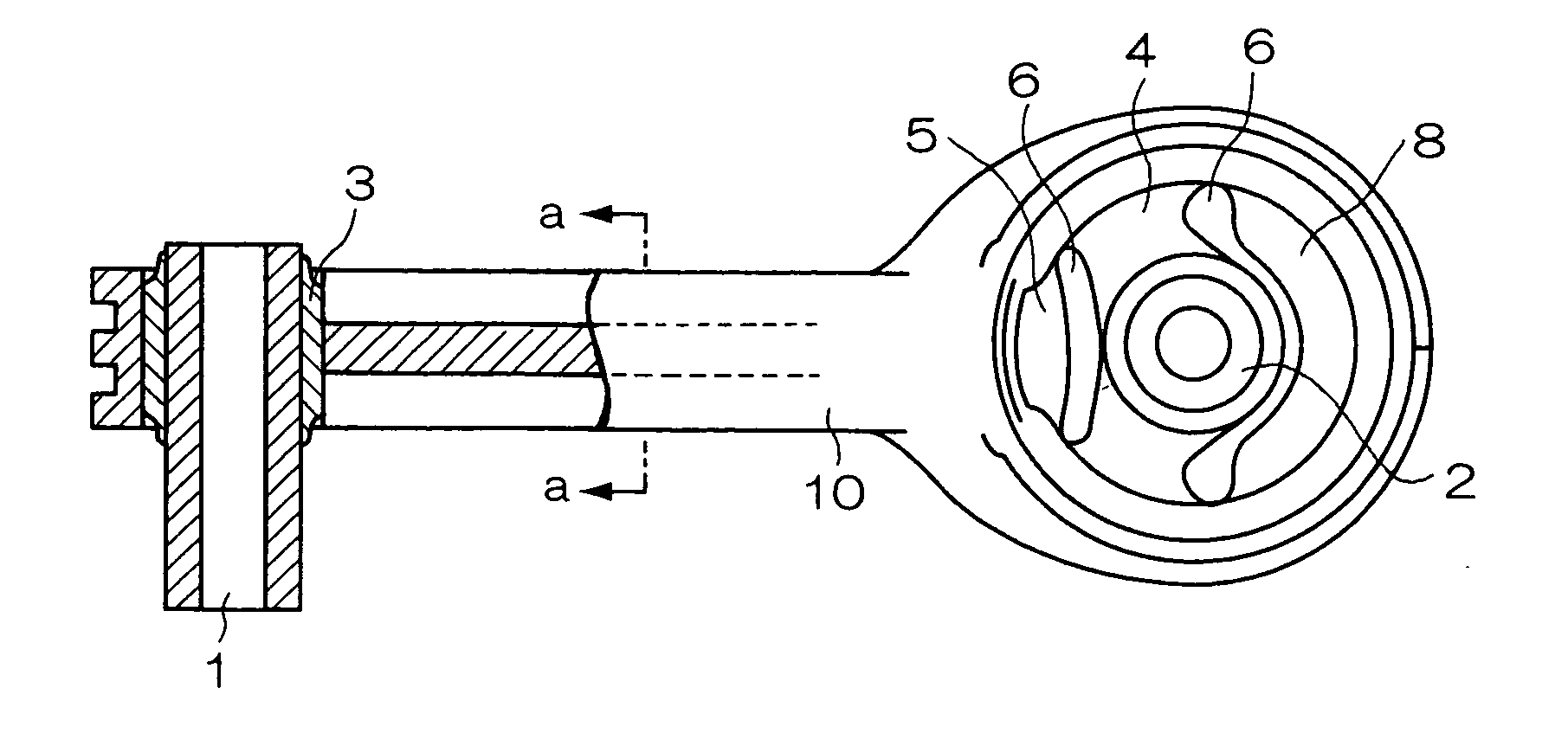
TECHNICAL FIELD [0001] The present invention relates to a torque rod for arresting the movement of an engine of a motor vehicle, and related to improving torque rods made of resin or metal that connect a pair of rubber bushes or cylinders. BACKGROUND ART [0002] Conventionally with torque rods, there is, as shown in FIG. 1A, a torque rod 10, connecting a pair of rubber bushes 3,4 and cylinders 1,2, is usually made of resin, iron or aluminum. The core of the rod portion is either a rectangular cross-sectional shape or H section cross section ribbed structure (see FIG. 1B and the patent publication reference 1). 6 are hollow portions, 5,8 are rubber stoppers, 9 is a rib formed on the surface. FIG. 1B is the cross section of FIG. 1A at the line “a-a”. [0003] However, for such a torque rod 10, whilst this can satisfy the requirements in terms of raising the compression strength and tensile strength, it is not a shape which takes into account other requirements. For example, the current s...

Claims


Application Information

Patent Timeline
Patent Type & Authority Applications(United States)
IPC IPC(8): F16C7/02B60G7/00B60K5/12F16C7/04F16F1/38F16F15/08
CPCB60G7/001B60K5/1241Y10T74/2142F16F1/3849F16C7/04B60G2206/11B60G2206/7104F16C2326/05
Inventor KAMEI, NAOYUKIKOJIMA, HIROSHI
Owner HONDA MOTOR CO LTD
Learn More