
Vehicle start control device and method

a control device and start technology, applied in the direction of gearing control, gearing element, belt/chain/gearing, etc., can solve the problems of not being able to rotate the wheel, and the engagement shock may be greater than the shock generated in the normal state, so as to suppress the generation of shock

Inactive Publication Date: 2007-11-22
TOYOTA JIDOSHA KK
View PDF5 Cites 36 Cited by
  • Summary
  • Abstract
  • Description
  • Claims
  • Application Information

AI Technical Summary

Benefits of technology

The present invention provides a vehicle start control device and method that can execute both a neutral control and a hill hold control. The device includes a neutral release mode controller that increases the torque transfer capacity of the coupling device between the engine and drive wheels when the neutral control is executed, so that the engine idling load is reduced. The device also includes a drive feel improving function that can suppress generation of shock when the neutral control is released under the hill hold control. The invention can improve the vehicle start control device by increasing the torque transfer capacity of the coupling device in a gradual manner and reducing the magnitude of the torque transfer capacity under the hill hold control. This allows for a smooth engagement of the coupling device and reduces unintentional behavior of the motor vehicle. The invention can also improve the vehicle start control device by increasing the torque transfer capacity of the coupling device when the neutral control is executed and reducing the magnitude of the torque transfer capacity under the hill hold control.

Problems solved by technology

Thus, the wheels are not allowed to rotate when the input clutch is fully engaged.
This leaves a possibility that the torque reaction attributable to the engagement of the input clutch may not be reduced and the engagement shock may become greater than that generated in the normal state.

Method used


Image

  • Vehicle start control device and method
  • Vehicle start control device and method
  • Vehicle start control device and method

Examples


Embodiment Construction

[0049]Various embodiments of the present invention will now be described in detail with reference to the accompanying drawings.

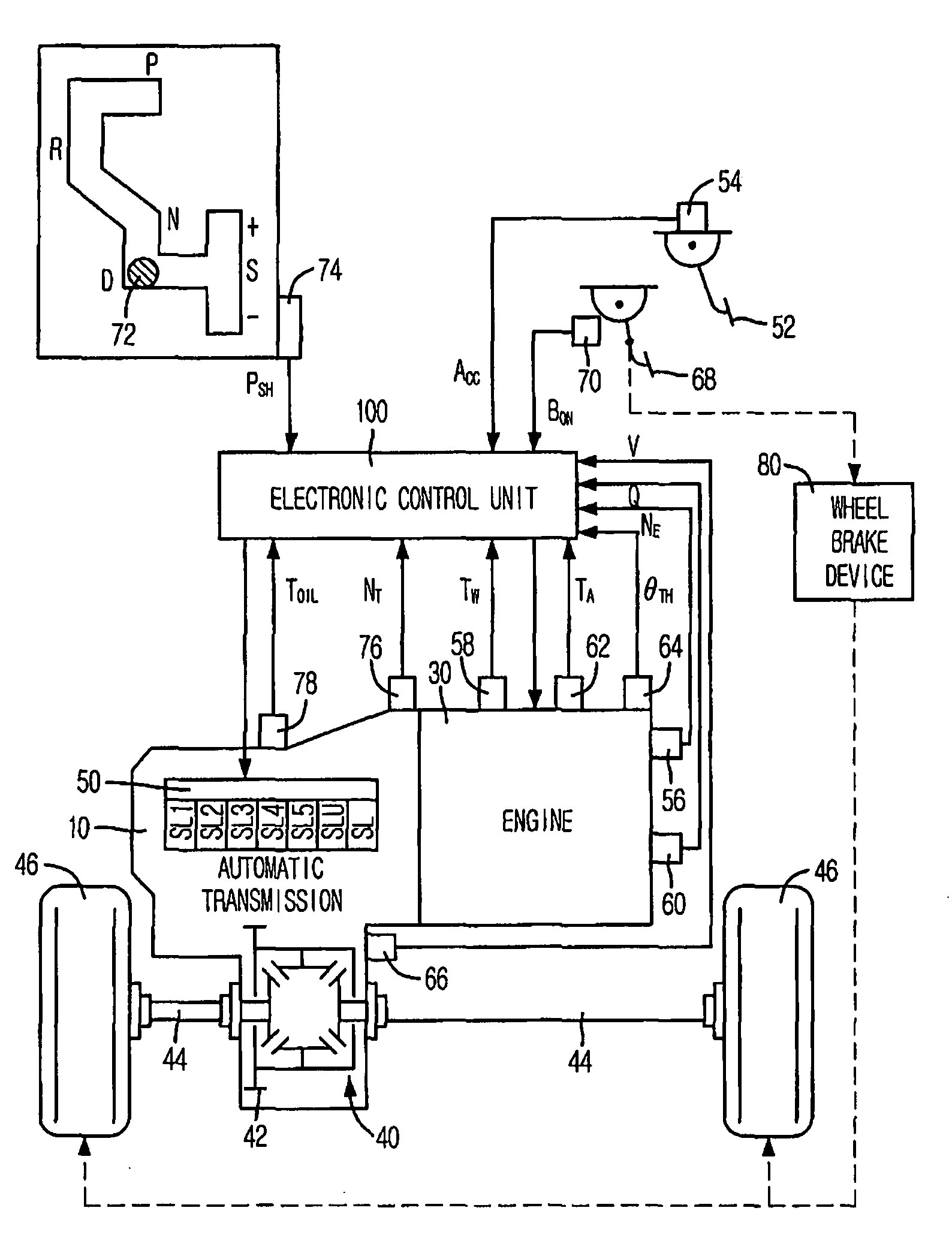
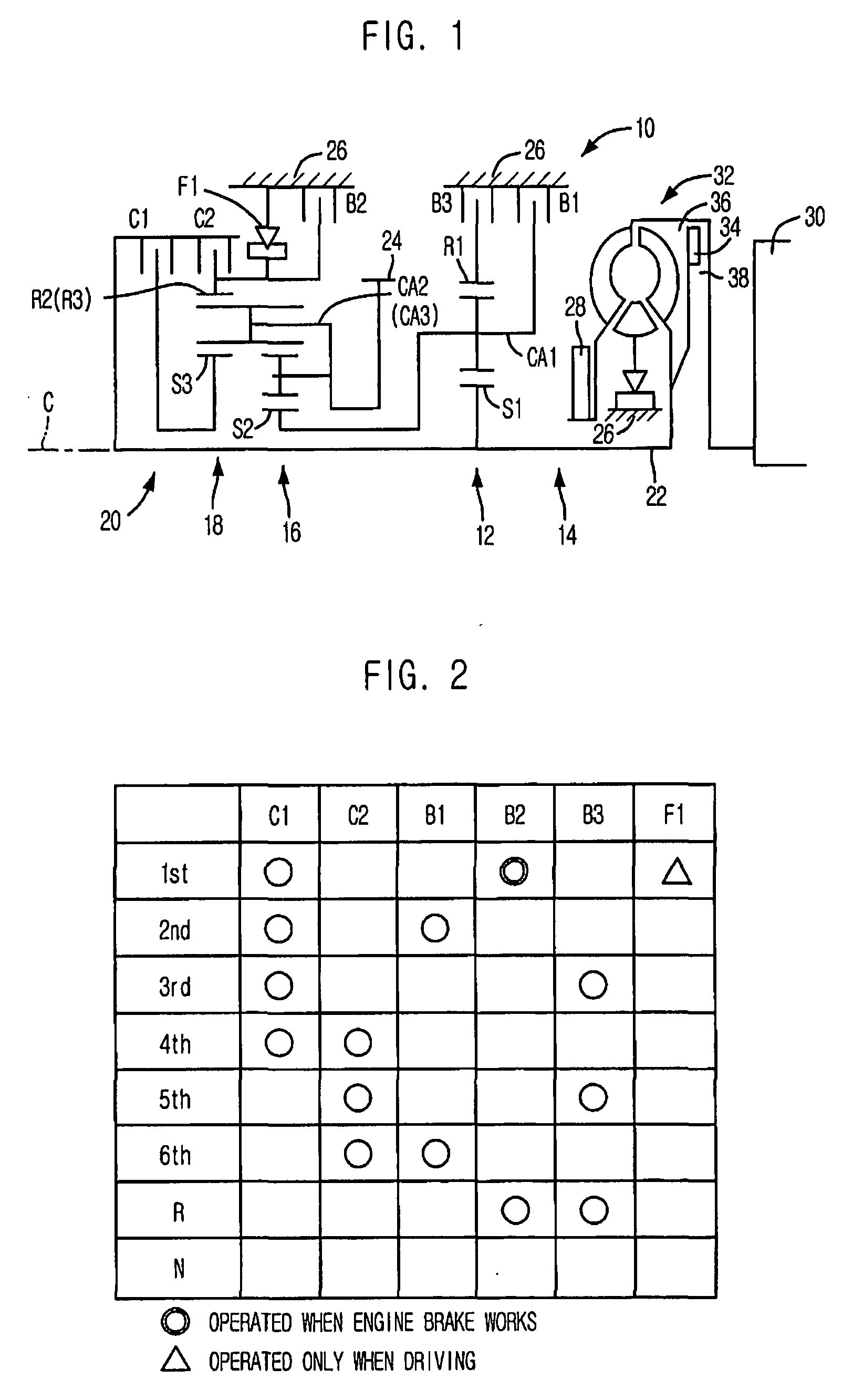
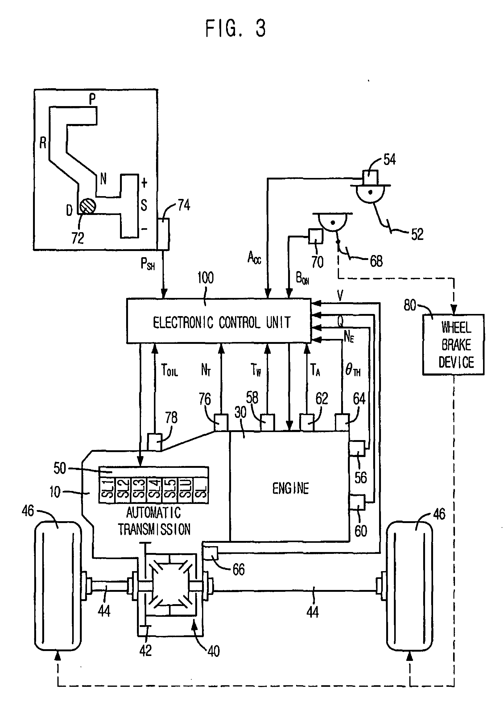
[0050]FIG. 1 is a schematic diagram showing an automatic transmission 10 for a motor vehicle (hereinafter simply referred to as “automatic transmission”). FIG. 2 is an operation table illustrating operation states of friction-coupling elements, i.e., friction-coupling devices, at different speed ratios. The automatic transmission 10 may be adapted for optimal use in a front-engine front-wheel drive (FF) vehicle in which the automatic transmission 10 is mounted transversely. The automatic transmission 10 includes a transmission case 26 that serves as a non-rotating member fixed to the vehicle body; a first transmission unit 14, received within the transmission case 26 and mainly composed of a single-pinion type first planetary gear set 12; and a second transmission unit 20 of a Ravigneaux type, received within the transmission case 26 and mainly composed of a...


PUM


Abstract

A vehicle start control device executes a neutral control and a hill hold control, wherein, in the neutral control, a clutch provided in a power transmission path is brought into a slipping state or a released state to reduce the engine idling load and in the hill hold control, a brake force is generated to hold the vehicle against movement on a hill. A neutral release mode controller is employed to increase a torque transfer capacity of the clutch so that the clutch is engaged more gently when the neutral control is released under the hill hold control than in case of releasing the neutral control when the hill hold control is not executed. This suppresses generation of a shock that would be caused by engagement of the clutch when the neutral control is released under the hill hold control.

Description

INCORPORATION BY REFERENCE[0001]The disclosure of Japanese Patent Application No. 2006-141555 filed on May 22, 2006 including the specification, drawings, and abstract, is incorporated by reference in its entirety.BACKGROUND OF THE INVENTION[0002]1. Field of the Invention[0003]The present invention relates to a vehicle start control device and method that executes a neutral control and a hill hold control and, more particularly, that releases the neutral control.[0004]2. Description of the Related Art[0005]There is known a vehicle start control device that performs a neutral control and a hill hold control. In a neutral control, if predetermined neutral control conditions are satisfied while a shift position of a transmission is a drive position, e.g., if a foot brake is operated when the vehicle speed is zero, a coupling device provided in the power transmission path between the engine and the drive wheels is slipping or is released. Thus, the power transmission path is kept in a p...

Claims


Application Information

Patent Timeline
Patent Type & Authority Applications(United States)
IPC IPC(8): B60W10/02F16H59/70F16H61/02F16H61/68F16H61/684F16H61/686
CPCB60W10/02Y10T477/78B60W30/18118
Inventor INOUE, DAISUKETANIGUCHI, HIROJI
Owner TOYOTA JIDOSHA KK
Learn More