System and method for optical section image line removal

a technology of optical section and image line, applied in the field of systems, can solve the problems of not directly determining phase angles, adding to the obtained image unwanted grid patterns, and not accurately obtaining the desired phase angles

Inactive Publication Date: 2007-11-22
GE HEALTHCARE BIO SCI CORP
View PDF14 Cites 9 Cited by
  • Summary
  • Abstract
  • Description
  • Claims
  • Application Information

AI Technical Summary

Benefits of technology

[0012]Embodiments of the present invention relate to an apparatus, computer system, and method for generating an image via optical sectioning by determining phase angles of a grid pattern projected successively onto an object to be imaged. Embodiments of the present invention relate to an apparatus, computer system, and method for generating an image based on phase angles of a grid pattern that are set or determined with reference to pixel values that are logarithmic values or approximate logarithmic pixel values of actually recorded pixel values. Embodiments of the present invention relate to an apparatus, computer system, and met

Problems solved by technology

While projecting the grid pattern onto the object allows for removal of those pixels that are not of the desired plane of the object, it also adds to the obtained image an unwanted grid pattern.
Further, the phase angles are not directly determined.
This procedure does not allow for accurately obtaining the desired phase angles.
Further, the instance where the artefact signal is below the threshold cannot be accurately determined using FFT, in particular considering the low accuracy of FFT, which can be attributed at least in part to the measurement of the signal power in discrete values.
Accordingly, the measurement of the intensity of the artefact is often incorrect.
Such change in intensities results in a non-cancellation of the grid pattern of the three images when combined.
Additionally, while the combination of the three images allows for the removal of grid lines, the procedure does not yield an optimal image.

Method used


Image

  • System and method for optical section image line removal
  • System and method for optical section image line removal
  • System and method for optical section image line removal

Examples


Embodiment Construction

Direct Calculation of Phase Angle

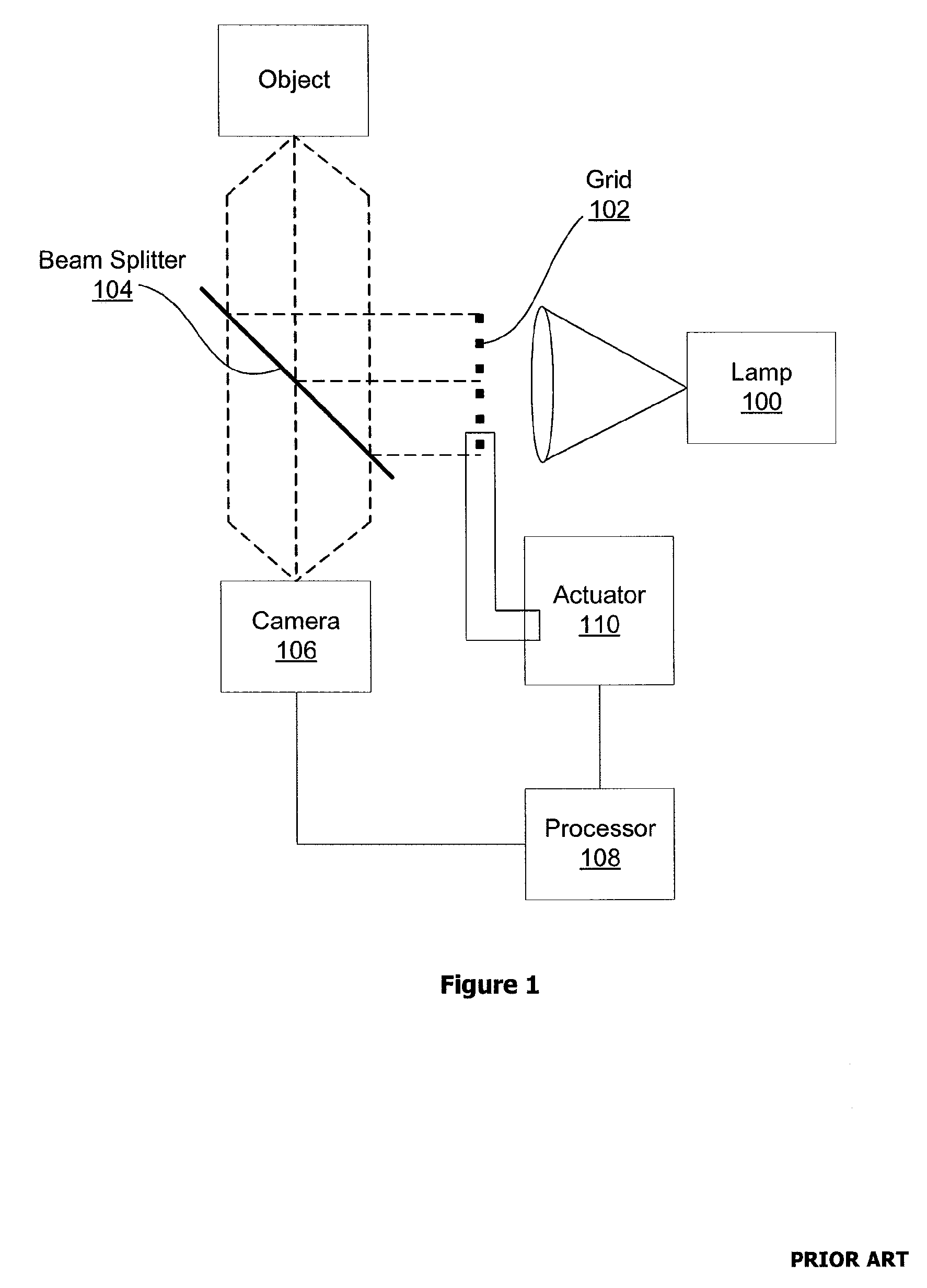
[0030]FIG. 3 illustrates components of an imaging system according to an embodiment of the present invention. Elements of FIG. 3 which are described above with respect to FIG. 1 are provided with the same reference numerals. Referring to FIG. 3, in an embodiment of the present invention, for obtaining an image of an object, the grid 102 may be moved by the piezo-electrically driven actuator 110 into three different positions. It will be appreciated that an actuator other than a piezo-electrically driven actuator may be used. Each position may be at a different phase angle. For each of the three positions, the camera 106, e.g., a CCD (charge-coupled device) camera or other conventional camera, may record a corresponding image including grid lines. The processor 108, which may be any suitably appropriate computer processor or equivalent thereof, may generate an output image based on the three recorded images. The processor 108 may be of any suitably ap...


PUM


Abstract

An apparatus, system, and method for generating an image are disclosed. A processor may generate a first output image based on a plurality of input images and remove an artefact, if any, from the first output image to generate a second output image. For example, in an embodiment, the processor may calculate a contribution of the artefact to image intensity values and subtract the calculated contribution from the image intensity values. In another embodiment, the processor may delete a predetermined portion of a transform image representing transform data obtained by applying an image transform to the first output image, thereby modifying the transform data, and may generate a non-transform image based on the modified transform data.

Description

FIELD OF THE INVENTION[0001]This invention relates to a system for removing a line from a section of an optical image.BACKGROUND OF THE INVENTION[0002]Obtaining a two dimensional image of a three dimensional object is often desired, for example, for the study of organisms. Imaging of the object is often conducted via a microscope. Clarity of the image is enhanced by imaging a particular two dimensional plane, a slice, of the three dimensional object.[0003]Conventional systems generate an image of the two dimensional plane in the three dimensional object in several different ways, including deconvolution, confocal laser scanning, and optical sectioning. For optical sectioning, conventional systems project a grid pattern onto a particular plane in the three dimensional image, and construct an image out of only those pixels in which the grid pattern falls. The plane is one selected with respect to an objective. The plane of the object to be imaged depends on the object's placement with...

Claims


Application Information

Patent Timeline
IPC IPC(8): G06K9/36
CPCG01B11/25H04N13/0253H04N13/0207G02B21/367A61B6/5258H04N13/254H04N13/207
Inventor RUANAIDH, JOSEPH J.O.ZHANG, YANGEMERIC, PIERRESWIATEK, MARCIN R.ROZENFELD, VADIM
Owner GE HEALTHCARE BIO SCI CORP
Why Eureka
Try Eureka