
Automating tuning of a closed loop controller

Active Publication Date: 2007-11-22
SIEMENS IND INC
View PDF17 Cites 29 Cited by
  • Summary
  • Abstract
  • Description
  • Claims
  • Application Information

AI Technical Summary

Benefits of technology

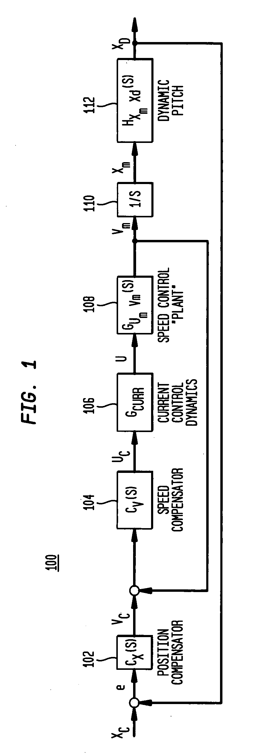
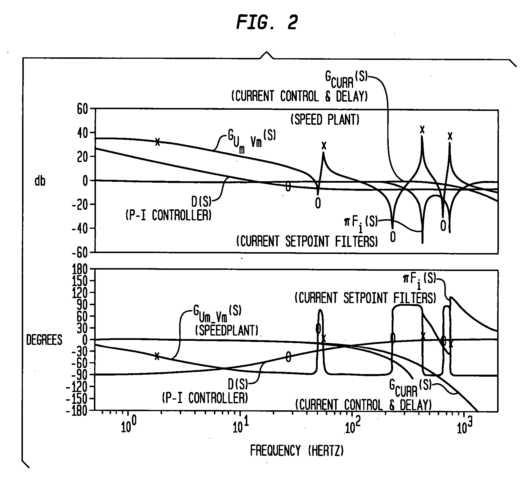
[0007] The present invention is a novel device, system, and method for simultaneous selection of filters and loop proportional gain for a closed loop system. According to an exemplary embodiment of the present invention, the method may generate a Frequency Response Function (FRF) of the system. The method may determine one or more resonant and anti-resonant frequencies of a speed controller of the system and estimate the total inertia of the system. The method may generate a Frequency Response Function for a current controller and loop pure time delays for the system. The method may determine a lower limit, an upper limit, and an initial candidate value for proportional gain (Kp) based on the estimated total inertia and FRF of the current controller and loop pure time delays and set a candidate value equal to the initial candidate value. The method may generate a complete Frequency Response Function that represents the system plant's Frequency Response Function multiplied by the current controller Frequency Response Function and loop pure time delays Frequency Response Function and the candidate value for Kp. The

Problems solved by technology

The Moser patent does not offer any guidelines for iterating the filter selection parameters.
The two components of the compensator are determined separately, thus the interaction is not considered and the result will be less than optimal.
Finally it does not offer suggestions of how to represent the concepts and algorithms in terms of object classes.

Method used


Image

  • Automating tuning of a closed loop controller
  • Automating tuning of a closed loop controller
  • Automating tuning of a closed loop controller

Examples


Embodiment Construction

[0015] A set of methods for automated selection of the portion of the controller known as the speed loop compensator is disclosed. Specifically, outlined is a methodology for simultaneous selection of filters and loop proportional gain for systems that exhibit resonance effects. The exemplary methods operate on a Frequency Response Function (FRF) that represents the dynamic response from an actuation force (e.g. motor torque) to the sensor used for feedback of speed control (e.g. motor encoder angle). The FRF may be represented as a series of complex numbers each with a corresponding frequency value. The tuning method may determine the combination of filter parameters that allows the loop proportional loop gain (Kp) to be maximized while meeting a specified set of criteria for stability margins. Methods for selecting integral gain and reference model are also presented. The methods may be implemented in an object oriented software environment in order that the software implementatio...


PUM


Abstract

The present invention is a novel device, system, and method for simultaneous selection of filters and loop proportional gain for a closed loop system. According to an exemplary embodiment of the present invention, a method provides an automated selection of the portion of the controller known as the speed loop compensator. The method may operate on a frequency response function that represents the dynamic response from an actuation force (e.g. motor torque) to the sensor used for feedback of speed control (e.g. motor encoder angle). The frequency response function may be represented as a series of complex numbers each with a corresponding frequency value. The tuning method determines the combination of filter parameters that allows the loop proportional loop gain (Kp) to be maximized while meeting a specified set of criteria for stability margins. Methods for selecting integral gain and reference model are also presented.

Description

CROSS-REFERENCE TO RELATED APPLICATIONS [0001] This application claims priority to U.S. Patent Application No. 60 / 801,959 filed May 19, 2006 entitled “Method for Automating Tuning of a Closed Loop Controller”, and to U.S. Patent Application No. 60 / 801,946 filed on May 19, 2006 entitled “Method for Automating Tuning of a Closed Loop Controller by Selection of Filtering Parameters”, which are incorporated fully herein by reference.TECHNICAL FIELD [0002] The present invention relates to analyzing a frequency response function and more particularly, to a device, method, and system for selection of filters and loop proportional gain for a closed loop system. BACKGROUND INFORMATION [0003] Deployment of filters, proportional gains, and integral gains to comprise a speed controller's compensation equations is well established and this particular invention does not make new proposals in terms of the form or type of equations that execute in the control itself. Automation of “servo tuning” or...

Claims


Application Information

Patent Timeline
IPC IPC(8): H03D3/02G05B13/02
CPCG05B13/042H02P23/0077G05B2219/42152
Inventor YUTKOWITZ, STEPHEN J.
Owner SIEMENS IND INC
Learn More