Device and Method for Controlling Internal Combustion Engine with Universal Valve Gear System and Variable Compressing Mechanism

a technology of universal valve gear system and internal combustion engine, which is applied in the direction of electric control, machines/engines, output power, etc., can solve the problems of engine damage, valve and piston colliding, and the actual intake air amount following the desired intake air amount, so as to improve the response speed of the intake air amount, the effect of improving the accuracy of the actual intake air amoun

Inactive Publication Date: 2007-11-22
HONDA MOTOR CO LTD
View PDF2 Cites 4 Cited by
  • Summary
  • Abstract
  • Description
  • Claims
  • Application Information

AI Technical Summary

Benefits of technology

[0010] According to one aspect of the invention, a control apparatus for an engine having a variable lift mechanism that is capable of changing a lift amount of a valve and a variable compression ratio mechanism that is capable of changing a compression ratio in a combustion chamber is provided. The control apparatus controls the variable lift mechanism and the variable compression ratio mechanism so that a rate that the compression ratio decreases is faster than a rate that the lift amount increases when a requested engine output is increasing. The control apparatus further controls the variable lift mechanism and the variable compression ratio mechanism so that a rate that the lift amount decreases is faster than a rate that the compression ratio increases when the requested engine output is decreasing. According to the invention, a collision between the valve and the piston can be avoided while the intake air amount corresponding to the requested engine amount is implemented.
[0011] According to one embodiment of the invention, a variable phase mechanism that is capable of changing a phase of the valve is provided. The control apparatus controls the variable compression ratio mechanism and the variable phase mechanism so that a rate that the compression ratio decreases is faster than a rate that the phase is retarded when the requested engine output is increasing. The control apparatus controls the variable compression ratio mechanism and the variable phase mechanism so that a rate that the phase is advanced is faster than a rate that the compression ratio increases when the requested engine output is decreasing. According to the invention, a collision between the valve and the piston can be avoided while the intake air amount corresponding to the requested engine amount is implemented.

Problems solved by technology

However, as shown in FIG. 24(d), when the compression ratio is high, the lift amount of the valve may become large, for example, in a transient condition of a valve driving system and / or a compression ratio mechanism.
If such a high lift occurs when the compression ratio is high, the valve and the piston may collide with each other.
Such a collision may cause damage in the engine.
However, if such a recess is provided in the piston, the shape of the upper portion of the piston is complicated, which may cause deterioration in the combustion.
In an engine having such a valve driving system and a variable compression ratio mechanism, the following problems may arise.

Method used


Image

  • Device and Method for Controlling Internal Combustion Engine with Universal Valve Gear System and Variable Compressing Mechanism
  • Device and Method for Controlling Internal Combustion Engine with Universal Valve Gear System and Variable Compressing Mechanism
  • Device and Method for Controlling Internal Combustion Engine with Universal Valve Gear System and Variable Compressing Mechanism

Examples


Embodiment Construction

[0047] Structure of Engine and Control Unit

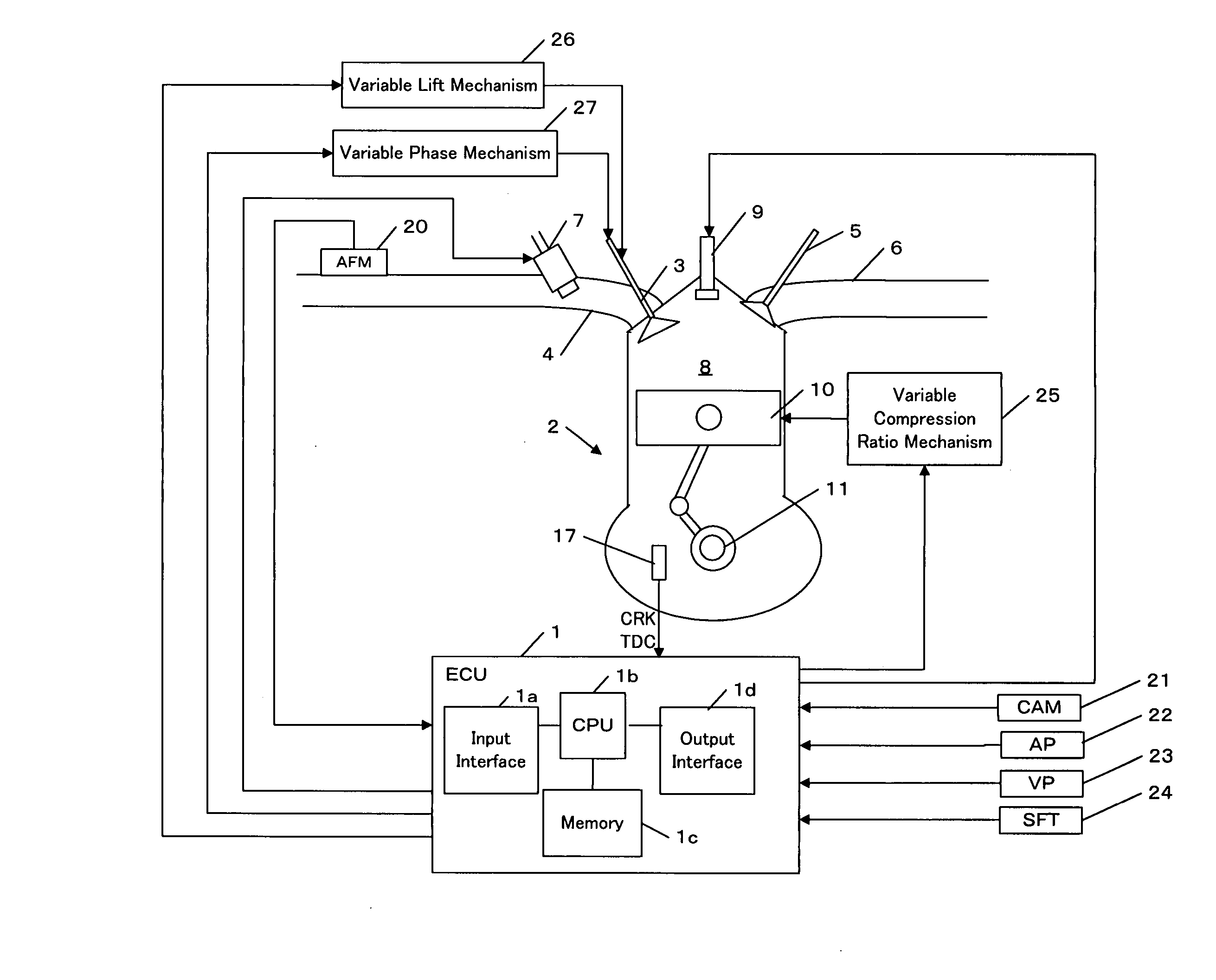
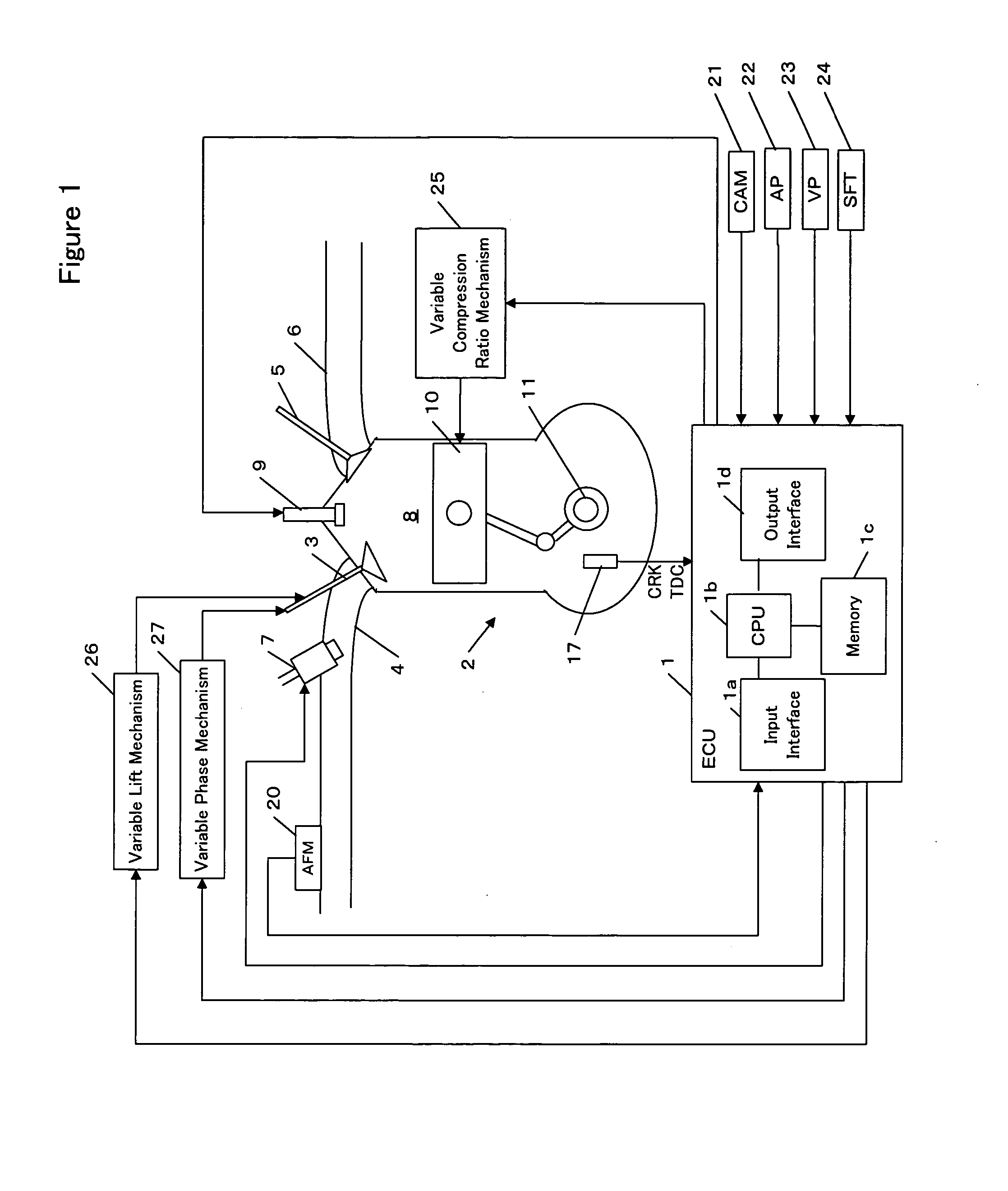
[0048] Referring to the drawings, specific embodiments of the invention will be described. FIG. 1 is a block diagram showing an engine and a control unit for the engine in accordance with one embodiment of the invention.

[0049] An electronic control unit (hereinafter referred to as an ECU) 1 comprises an input interface 1a for receiving data sent from each part of the vehicle, a CPU 1b for carrying out operations for controlling various parts of the vehicle, a memory 1c including a read only memory (ROM) and a random access memory (RAM), and an output interface 1d for sending a control signal to various parts of the vehicle. Programs and various data for controlling each part of the vehicle are stored in the ROM. A program and data for implementing a control in accordance with the invention are stored in the ROM. The ROM may be a rewritable ROM such as an EPROM. The RAM provides work areas for operations by the CPU 1b, in which data sent f...


PUM


Abstract

A control device for controlling an engine, comprising a variable lift mechanism capable of changing the lift of a valve and a variable compression ratio mechanism capable of changing a compression ratio in a combustion chamber. The control devise controls the variable lift mechanisms and the variable compression ratio mechanism so that, when a requested engine output is increased, a compression ratio decreasing rate is increased over a lift increasing rate and, when the requested engine output is reduced, a lift decreasing rate is increased over a compression ratio increasing rate. When the engine comprises a variable phase mechanism capable of changing the phase of the valve, the control devise controls the variable compression ratio mechanism and the variable phase mechanism so that, when the requested engine output is increased, the compression ratio decreasing rate is increased over the change rate of the phase to a delay angle and, when the requested engine output is reduced, the change rate of the phase to an advance angle is increased over the compression ratio increasing rate. Thus, the contact of the valve with a piston can be avoided.

Description

BACKGROUND OF THE INVENTION [0001] The present invention relates to an apparatus and a method for controlling an internal combustion engine having a variable valve driving system and a variable compression ratio mechanism. [0002] Some of valve driving systems for an internal combustion engine (referred to as an engine hereinafter) are capable of variably controlling the amount of lift of an intake / exhaust valve. Through such control of the intake / exhaust valve, a desired engine output can be generated. On the other hand, a variable compression ratio mechanism for variably controlling a compression ratio in a combustion chamber of an engine has been proposed. [0003] Japanese Patent Application Unexamined Publication (Kokai) No. 2001-263099 discloses a scheme for preventing interference between a piston and an intake valve when a variable compression ratio mechanism for changing a compression ratio by changing the position of the top dead center (TDC) of the piston is used. According ...

Claims


Application Information

Patent Timeline
Patent Type & Authority Applications(United States)
IPC IPC(8): F01L1/047F02D15/02F02D13/02F02D41/04
CPCF02D13/0226Y02T10/42Y02T10/18F02D15/02Y02T10/12Y02T10/40F02D13/02
Inventor YASUI, YUJI
Owner HONDA MOTOR CO LTD
Why Eureka
Try Eureka