
Ship Hull and a Method of Manufacturing Such a Hull

Inactive Publication Date: 2007-11-22
FAGERDALA THIGER MARINE SYST
View PDF1 Cites 7 Cited by
  • Summary
  • Abstract
  • Description
  • Claims
  • Application Information

AI Technical Summary

Benefits of technology

[0009] Thus, it is an object of the present invention to provide a ship hull having improved deformation properties in the case of ground impacts and collisions, such that the risk of leakage is eliminated or at least substantially reduced.
[0010] Another object of the present invention is to provide a ship hull having improved buoyancy. Even in a damaged condition, it should float such that an oil cargo can be pumped over to another ship, or such that passengers can be evacuated from the disabled vessel.
[0011] A further object of the present invention is to provide a method of manufacturing a ship hull having improved deformation properties and an eliminated or at least substantially reduced risk of leakage in the case of ground impacts and collisions.
[0012] A further object of the present invention is to provide a method of manufacturing, or alternatively rebuilding a ship hull, making ships having this hull practically unsubmersible.
[0013] A further object of the present invention is to provide a method of manufacturing a ship hull that, regardless of hull shape, provides optimal fixation between different layers of the hull with a minimum of costs and without requiring accurate adjustments, such as e.g. mechanical measures in the form of grinding, cutting, or the like.
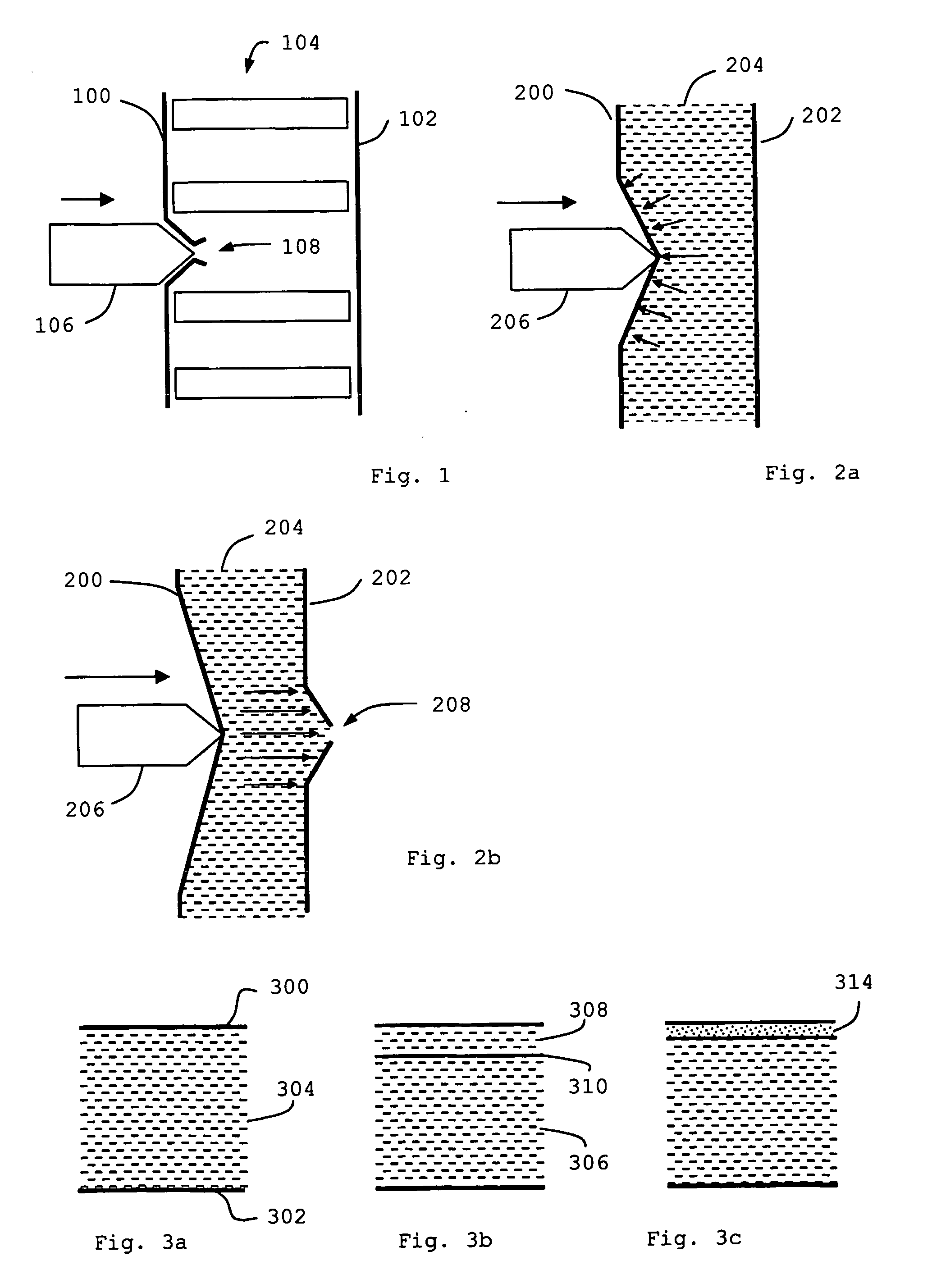
[0015] In particular, the invention refers to a ship hull, especially intended for oil and chemical ships, passenger ships and fishing ships, comprising an inner hull made of steel or aluminium built on a supporting structure of frames, stringers and longitudinals, and an outer hull. Between the inner hull and the outer hull a cellular plastic material is applied having chiefly closed cells for improved buoyancy and energy absorbing capability. The outer hull is made of a high strength steel, wherein at external strain the outer hull and the cellular plastic material are adapted to jointly constitute an energy absorbing deformation zone. The specific properties of the cellular plastic material entail that the deformation arising from the indentation of the outer hull at collision can be rapidly distributed over a fairly large area around this indentation. Then, a counter-pressure in the cellular plastic arises which, in combination with the high strength steel material of the outer hull, entails distribution of the indentation over a fairly large surface, such that a heavy local deformation of the outer hull is avoided.

Problems solved by technology

Although double hulls have evidently resulted in significantly increased security at low energy ground impacts, the solution is far from optimal.
The construction is significantly more expensive, and the lack of counter pressure from the water on the inner hull give rise to tension problems, whereas the significantly larger total plate area, which is approximately 2,5 times larger than for a single hull, give rise to increased corrosion problems and increased maintenance costs.
At mechanical stress on the outside of the outer hull, it is heavily deformed locally, resulting in cracks in the steel plate.
Moreover, the deformation is transferred by means of a framework between the hulls further on to the inner hull, which may also crack, resulting in leakage.
Further, there is an explosion risk due to the formation of gas between the outer and inner hulls as low viscous substances from the oil or similar is pressed through cracks and welding air holes due to the lack of a counter pressure, in contrast to single hulls when the water applies a counter pressure from the outside of the ship.
Therefore, the space between the hulls must be filled with inert gas, resulting in increased costs and the risk of leakage, as well as difficulties when inspecting the ship between the hulls.
However, the problems of external strain on a ship resulting in local deformation and penetration of the outer hull followed by leakage, are not dealt with herein.

Method used


Image

  • Ship Hull and a Method of Manufacturing Such a Hull
  • Ship Hull and a Method of Manufacturing Such a Hull
  • Ship Hull and a Method of Manufacturing Such a Hull

Examples


example

[0081] A PVC-foam having a density of 100 kg / m3 can be loaded by 280 tons per m2 before deformation occurs. This is the case without any surface layer on the top surface of the cellular plastic material. A PVC-foam having a density of 200 kg / m3 can be loaded by almost 500 tons per m2 before deformation occurs.

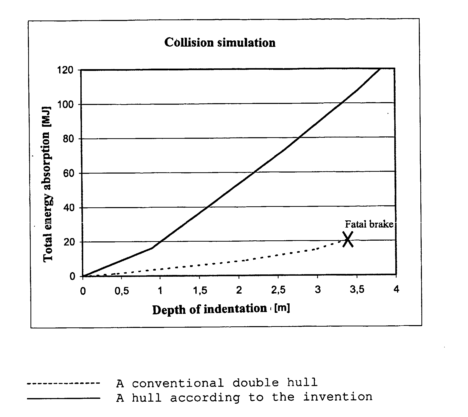
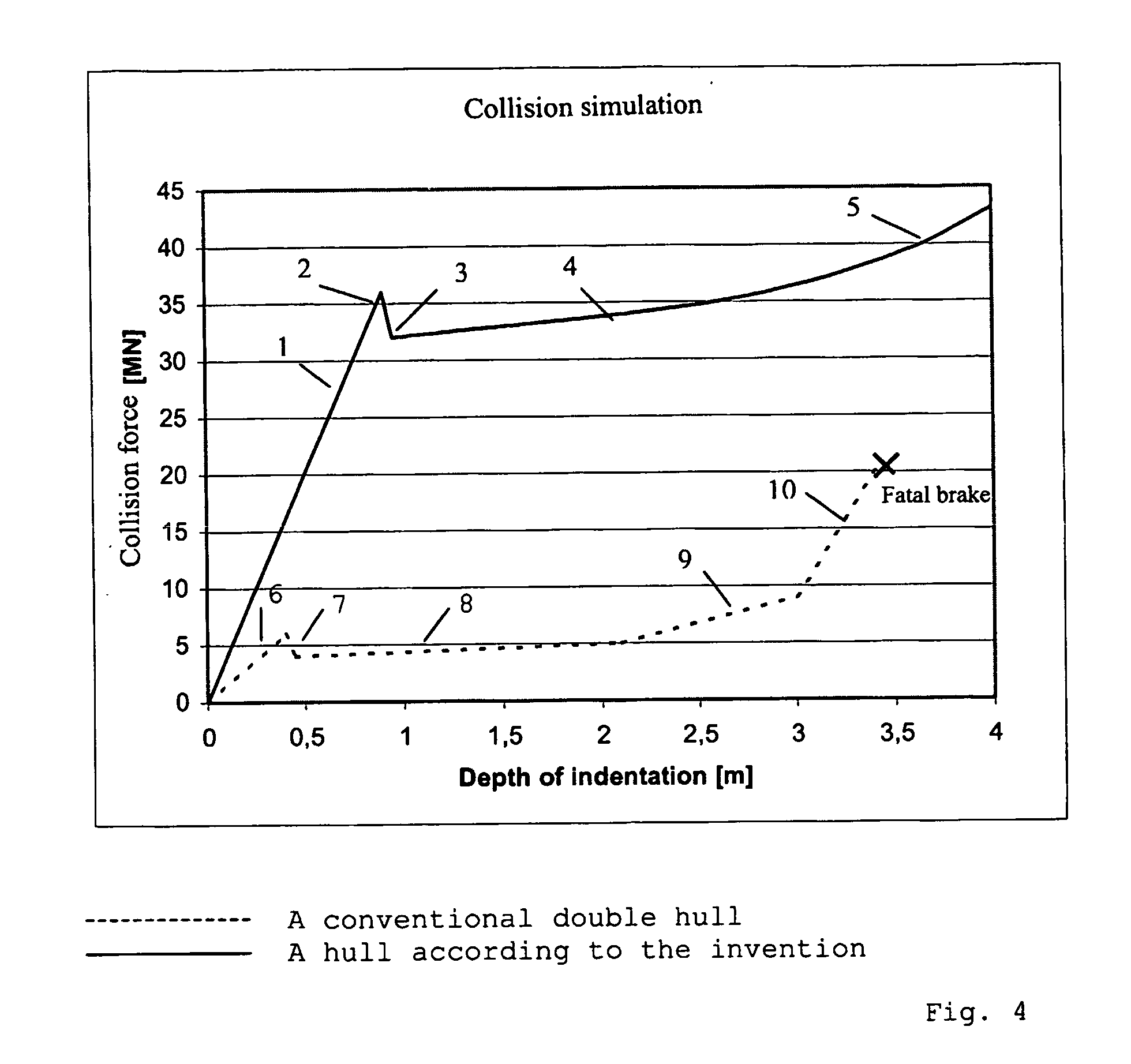
[0082] When deformation occurs, an outer layer is initially deformed, and in order to further deform the cellular plastic, the compressive force must be more than doubled. This fact combined with a hard surface layer on the cellular plastic surface which distributes a compressive force over a larger area, results in that the energy absorption capability of the structure according to the invention is extremely high.

[0083] When using expanded polypropylene or expanded polyethene, a further advantage is obtained in that, after compression, the cellular plastic material almost recovers its original thickness, however somewhat depending on the nature of the damage.

[0084] Yet anot...


PUM

PropertyMeasurementUnit
Thicknessaaaaaaaaaa
Thicknessaaaaaaaaaa
Thicknessaaaaaaaaaa

Abstract

A ship hull, especially intended for oil and chemical ships, passenger ships are fishing ships, comprising a hull made of steel or aluminium built on a supporting structure of frames, stringers and longitudinals, having improved buoyancy and energy absorbing capability, and a method of manufacturing such a ship. Between an outer hull (200) and an inner hull (202) a layer (204) of a cellular plastic material is applied having chiefly closed cells. The outer hull is made of a high strength steel, wherein at external strain the outer hull and the cellular plastic material are adapted to jointly constitute an energy absorbing deformation zone.

Description

FIELD OF THE INVENTION [0001] The invention relates to a ship hull having a double hull, particularly for oil and chemical ships, passenger ships and fishing ships, as well as a method of manufacturing such a hull. BACKGROUND OF THE INVENTION [0002] Ship hulls of today for merchant ships are without exception built as single or double hulls from plates on frames, stringers and longitudinals, regardless of the field of use. However, in order to obtain increased security, international rules has pushed the evolution towards double hulls. A typical distance between the outer hull and the inner hull is less than approximately 3 m. A framework is arranged between the hulls. [0003] Although double hulls have evidently resulted in significantly increased security at low energy ground impacts, the solution is far from optimal. The construction is significantly more expensive, and the lack of counter pressure from the water on the inner hull give rise to tension problems, whereas the signifi...

Claims


Application Information

Patent Timeline
IPC IPC(8): B63B3/20B32B15/08B63B3/10
CPCB32B15/08B63B3/20B63B3/10B32B7/12B32B2605/12B32B15/046B32B5/18B32B23/042
Inventor JONSSON, SVEN
Owner FAGERDALA THIGER MARINE SYST
Learn More