Connector, and portable terminal equipment including the connector

a technology of connectors and portable terminals, which is applied in the direction of coupling contact members, coupling device connections, printed circuits, etc., can solve the problems of easy disengagement of receptacles and plugs from each other, easy to reduce the holding force of receptacles with plugs, and easy to produce dust or shavings on plugs. , to achieve the effect of reducing the height of the connector, increasing the pressure on the plug contact by the recep

Inactive Publication Date: 2007-11-15
KYOCERA CORP
View PDF5 Cites 20 Cited by
  • Summary
  • Abstract
  • Description
  • Claims
  • Application Information

AI Technical Summary

Benefits of technology

[0028]The inner-wall-contacting portion is in contact with the inner wall of the receptacle body while being resiliently deformed, and accordingly, a high holding force for holding the engagement of the receptacle with the plug is achieved even if a further reduction in height of the connector is made because friction resistance is produced between the inner-wall-contacting portion and the inner wall of the receptacle body while the pressure exerted on the plug contact by the receptacle contact can be increased.
[0029]In addition, without using elements such as the movement preventive portions disclosed in JUPP 2001-338711, a height reduction of the connector is achieved, and the receptacle contact can be prevented from being curled up regardless of the position of the plug relative to the receptacle upon the plug being extracted from the receptacle.
[0030]Additionally, when the plug is inserted into and extracted from the receptacle in a state where the plug and the receptacle are inclined to each other by an angle exceeding a predetermined angle and when the connector is handled, either the position of the inner-wall contact portion or the receptacle contact does not change excessively even if a load greater than expected is exerted on the connector because the inner-wall-contacting portion is in contact with the inner wall of the receptacle body, so that a plastic deformation of the receptacle contact can be prevented from occurring. Consequently, the performance of the connector can be maintained with reliability.

Problems solved by technology

However, with this height reduction of the connector, the holding force for holding the engagement of the receptacle with the plug tends to decrease, which makes it easy for the receptacle and the plug to be undesirably disengaged from each other.
However, in the above described connector disclosed in JUPP 2001-338711, in which contacts of the receptacle are provided with lock lugs, the plug body of the plug, on which the engaging projections are formed, wear out over time as the plug is repeatedly inserted into and extracted from the receptacle, which causes the plug body of the plug to produce dust or shavings and further causes the engaging projections to be deformed to thereby lower the holding force for holding the engagement of the receptacle with the plug.
However, since this reduction deteriorates the strength of the movement preventive portions, there is a possibility of ends of the contacts of the receptacle not being prevented from being curled up.
Additionally, even if this curling can be prevented from occurring, there is a possibility of the contacts which are engaged with the pair of movement preventive portions not returning to their original positions; this type of connector in which the contacts of the receptacle no longer return to the original positions cannot make full use of the capabilities of the connector.

Method used


Image

  • Connector, and portable terminal equipment including the connector
  • Connector, and portable terminal equipment including the connector
  • Connector, and portable terminal equipment including the connector

Examples


Embodiment Construction

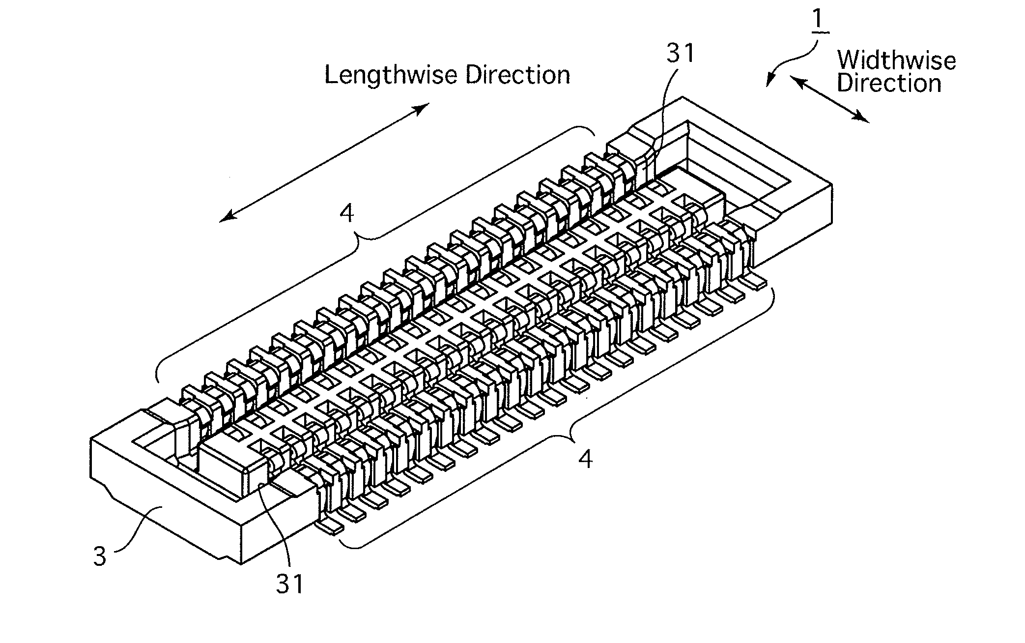
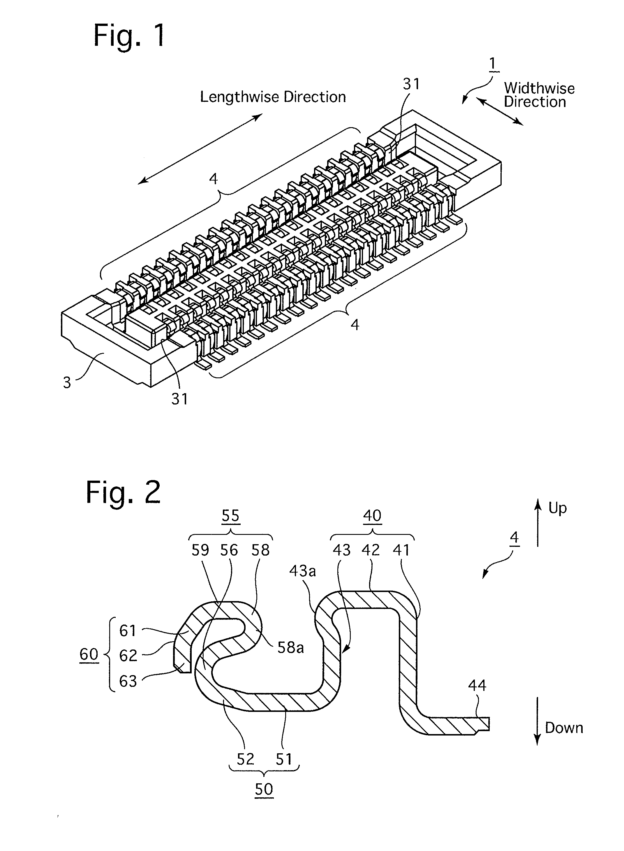
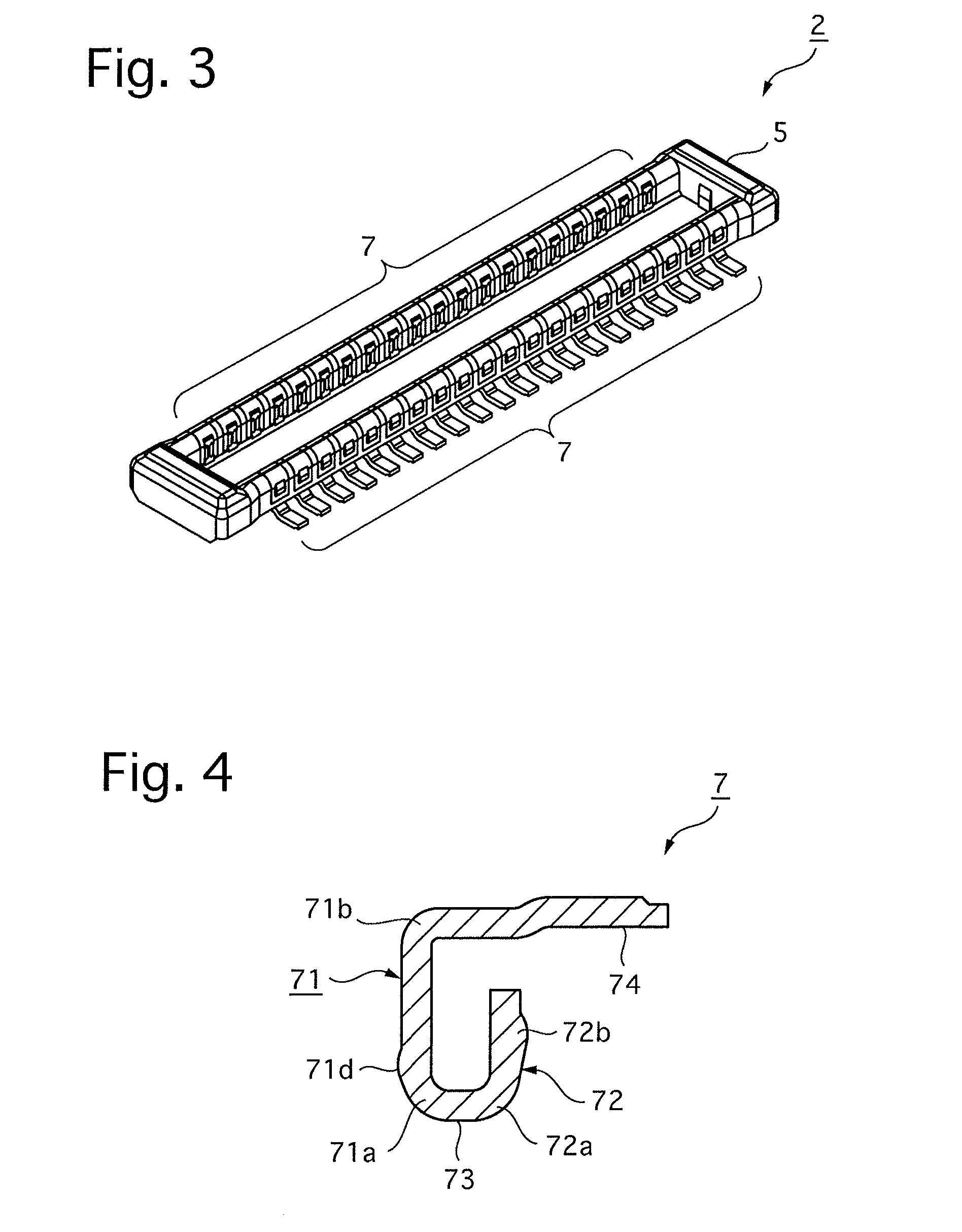
[0039]An embodiment of a connector according to the present invention is provided with a receptacle 1 (shown in FIG. 1) and an associated plug 2 (shown in FIG. 3) which are engaged with each other to be electrically connected to each other. For instance, one of the receptacle 1 and the plug 2 is mounted to an LCD (liquid display device / display device) unit or a CCD (charge coupled device / image pickup device) unit, while the other of the receptacle 1 and the plug 2 is mounted to a board (e.g., circuit board) which is electrically connected to the LCD unit or the CCD unit to control operations thereof. The LCD unit or the CCD unit is electrically connected to the board by the engagement of the plug 2 with the receptacle 1. The receptacle 1 and the plug 2 can be adopted for establishing electrical connection within portable terminal equipment (e.g., a cellular phone, a PDA (personal digital assistant) such as a mobile computer and the like) or electrical connection between portable t...


PUM


Abstract

A connector includes a plug including a plug body made of an insulating material and a plug contact; a receptacle including a receptacle body made of an insulating material and a receptacle contact, wherein the receptacle contact contacts the plug contact to be electrically connected with the plug contact when the plug is inserted into the receptacle; a plug-contact contacting portion formed on the receptacle contact for contacting the plug contact when the plug is inserted into the receptacle; an inner-wall-contacting portion extending from an end of the plug-contact contacting portion toward an inner wall of the receptacle body; and a contacting portion formed on the plug contact extending in a plug insertion/extraction direction. The first contacting portion slides on the plug-contact contacting portion and the inner-wall-contacting portion contacts the inner wall of the receptacle body when the plug is inserted in/extracted from the receptacle.

Description

CROSS REFERENCE TO RELATED APPLICATION[0001]The present invention is related to and claims priority of the following co-pending application, namely, Japanese Patent Application No. 2006-134997 filed on May 15, 2006.BACKGROUND OF THE INVENTION[0002]1. Field of the Invention[0003]The present invention relates to a connector including a receptacle and a plug which are engaged with each other to be electrically connected to each other.[0004]2. Description of the Prior Art[0005]In a conventional connector including a receptacle and a plug which are engaged with each other to be electrically connected to each other by inserting the plug into an insertion groove formed in the receptacle, a further reduction in height of the connector is now in increasing demand with the miniaturization of portable terminal equipment or other devices which adopt this type of connector. However, with this height reduction of the connector, the holding force for holding the engagement of the receptacle with t...

Claims


Application Information

Patent Timeline
Patent Type & Authority Applications(United States)
IPC IPC(8): H01R29/00
CPCH01R12/716H01R13/20H01R12/71
Inventor SASAKI, TOMOYA
Owner KYOCERA CORP
Why Eureka
Try Eureka