Backlight Inverter and Method of Driving Same

Inactive Publication Date: 2007-11-15
MINEBEA CO LTD
View PDF14 Cites 12 Cited by
  • Summary
  • Abstract
  • Description
  • Claims
  • Application Information

AI Technical Summary

Benefits of technology

[0019] Since the backlight inverter according to the present invention is adapted to operate at a frequency which is lower than an intermediate frequency between the series and parallel resonance frequencies of the resonant circuit formed at the secondary side of the inverter transformer, and which is higher than a frequency at which the phase characteristic curve has its peak, a stable lamp current flows without undergoing the influence of the lamp temperature, and the surface brightness of the LCD is stabilized immediately after cold starting.
[0020] Also, in the backlight inverter according to the present invention, the plurality of FET bridges and inverter transformers are controlled by one control IC for lighting the plurality of CCFLs thus achieving a low cost structure provided with a capability of performing a stable lamp current control (stable brightness of the LCD).
[0021] And, in the backlight inverter according to the present invention, since the inverter transformer is driven at the optimal operating frequency, the influence of the parasitic capacitance is reduced, and the uniformity of the lamp currents is enhanced. Consequently, the flickering at the LCD surface is reduced or eliminated.

Problems solved by technology

This drive by the resonance frequency, however, involves a phase difference between voltage and current at the primary side of the transformer and does not necessarily provide good power efficiency.
Also, a resonance frequency of a high order is found at the secondary side of the transformer, and it possibly happens that the transformer operates at such a resonance frequency or operates under the influence of such a resonance frequency, thus complicating the transformer designing.
Consequently, the turn number of windings, the air gap, and the degree of coupling are adjusted thus deteriorating the power efficiency, but the fluctuation of the output voltage due to the fluctuation of load impedance is reduced thus stabilizing the oscillation.
Since the driving method described above is adapted for lighting one CCFL or a couple of CCFLs, it is difficult for one backlight inverter to stably light more CCFLs, for example eight to sixteen CCFLs, and the lamp voltages of the individual CCFLs fluctuate causing fluctuation of the currents flowing in the parasitic capacitances of the CCFLs, which makes the brightness unstable causing the screen image of the LCD to flicker.
The substantial fluctuation of lamp impedance leads to fluctuation of lamp voltage, and consequently current flowing in the parasitic capacitance of the CCFL is caused to fluctuate.
As a result, the lamp current flowing in the CCFL is not stabilized, and the brightness becomes instable causing the screen image of the LCD to flicker.
This flickering problem may be simply solved if the lamp current is controlled by providing one control IC for each of the CCFLs, but this solution approach pushes up production cost of the backlight inverter significantly.

Method used


Image

  • Backlight Inverter and Method of Driving Same
  • Backlight Inverter and Method of Driving Same
  • Backlight Inverter and Method of Driving Same

Examples


Embodiment Construction

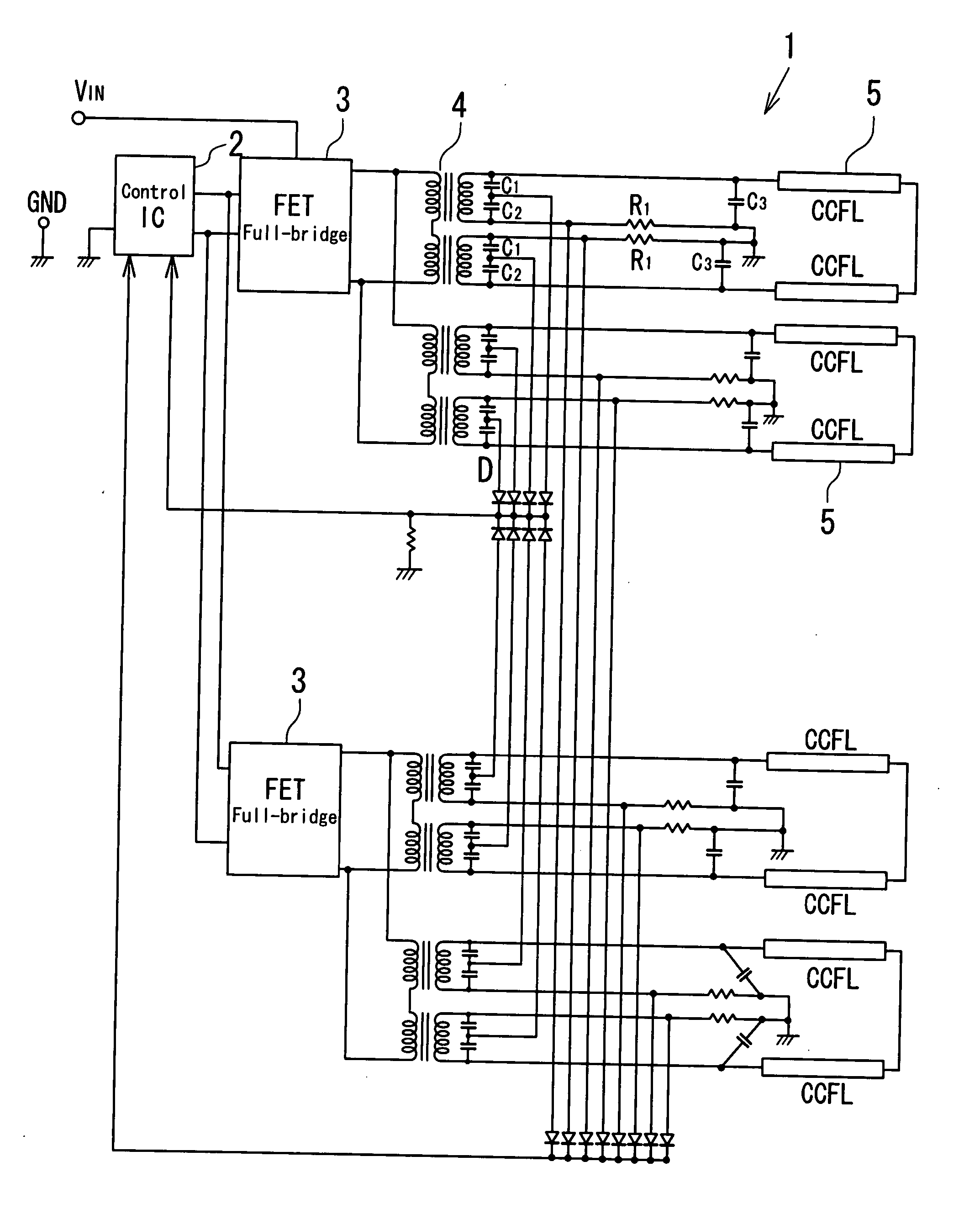
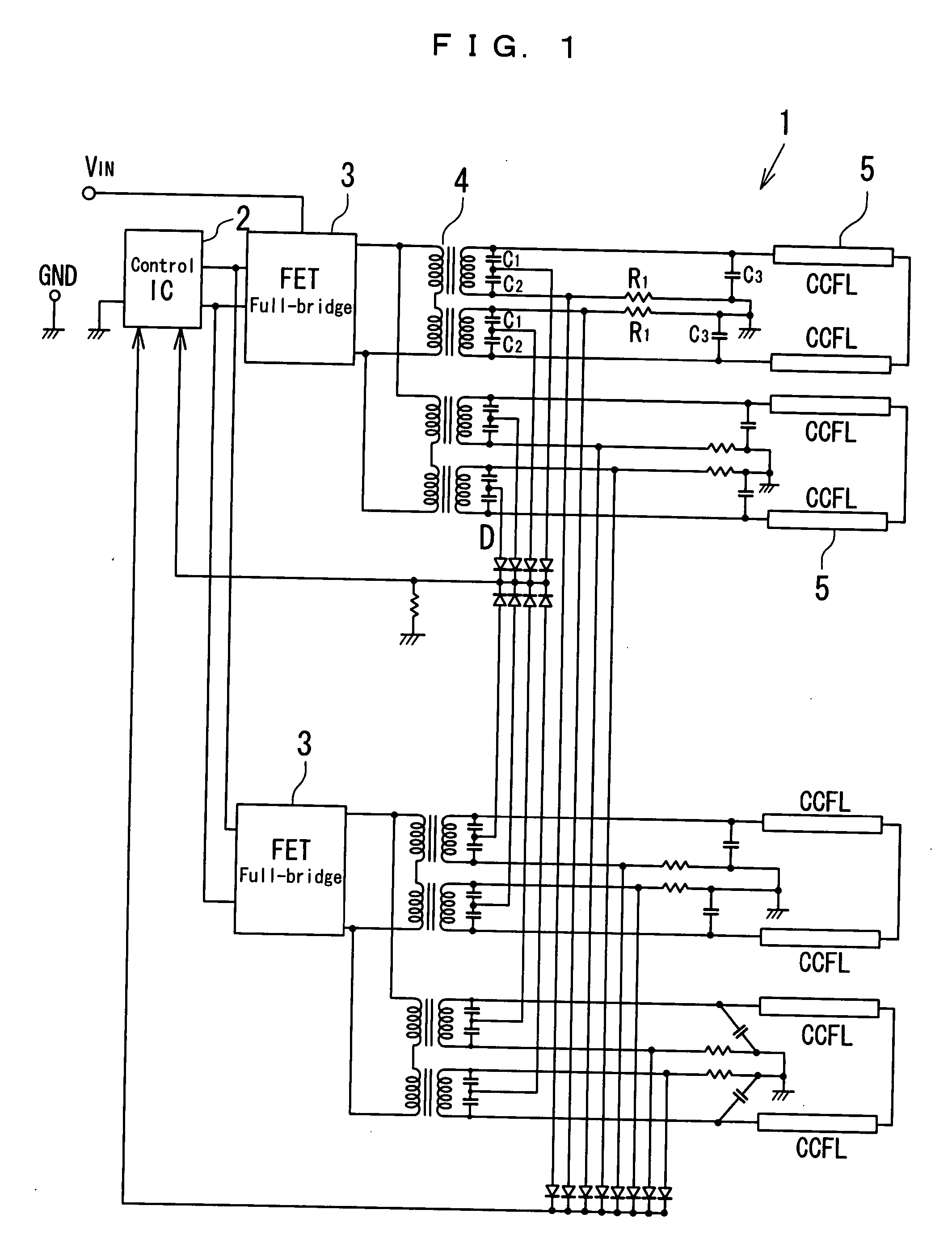
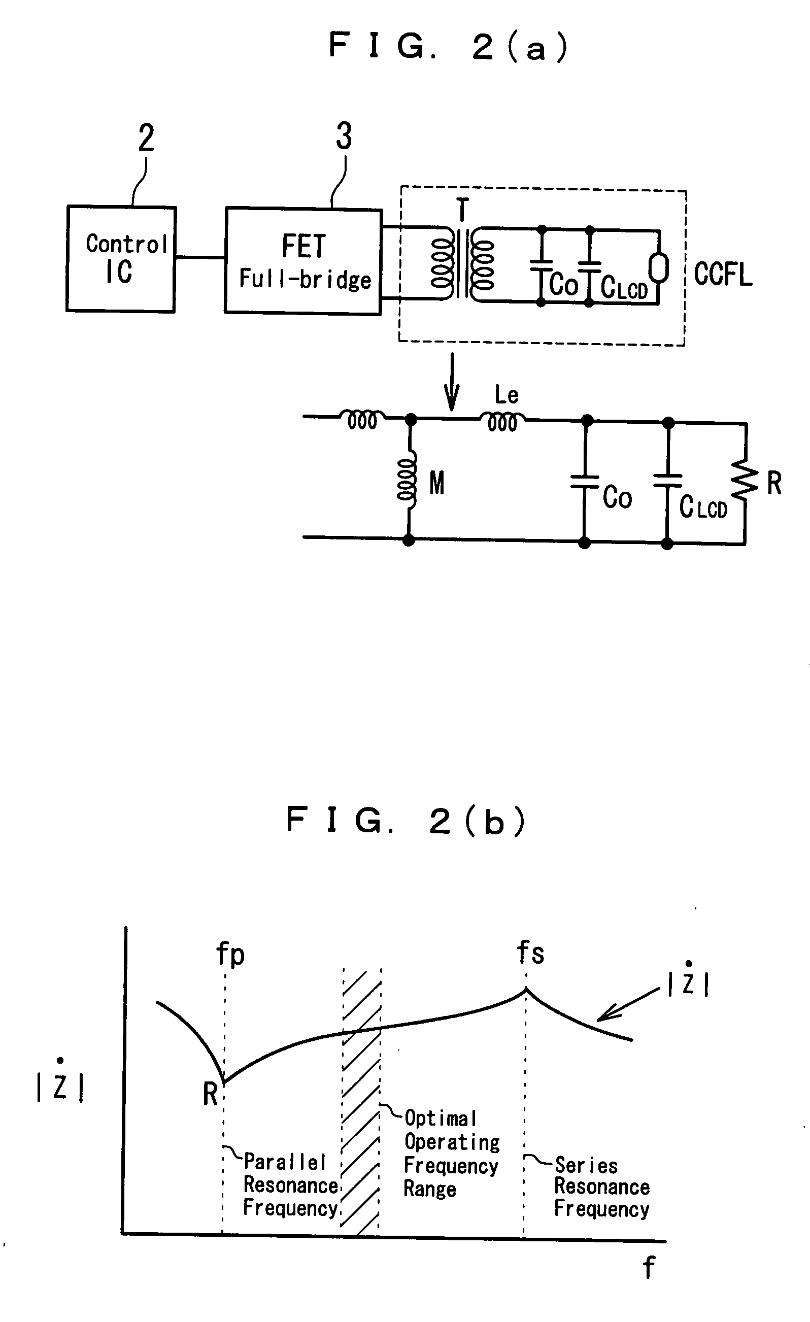
[0032] An exemplary embodiment of the present invention will be described with reference to the accompany drawings.

[0033] A backlight inverter 1 according to an embodiment of the present invention is for a large LCD television and includes one control IC 2, a plurality of FET full-bridges 3 activated by the control IC 2, and a plurality of inverter transformers 4 each two of which are connected to one each of the FET full-bridges 3 and each of which is adapted to light two CCFLs 5 connected in series to each other. Thus, the FET full-bridges 3 connected to the control IC2 to control the drive of the CCFLs 5, and the inverter transformers 4 are the main constituent portions of an inverter circuit.

[0034] Each of the FET full-bridge 3 is an H-bridge for driving load, composed of two series circuits which each include two FETs, namely a PMOS and an NMOS, and which are connected in parallel to each other, and is connected to the primary sides of two of the inverter transformers 4.

[003...


PUM


Abstract

A backlight inverter to light a plurality of CCFLs is provided which supplies a stable clamp current without influence of the CCFL temperature, and which stabilizes the LCD surface brightness immediately from the start of lighting the CCFLs, and a method of driving the backlight inverter is also provided. In a backlight inverter including a plurality of inverter transformers and adapted to light a plurality of CCFLs, two primary windings of each of the inverter transformers are connected in series to each other, and a resonant circuit is formed of a leakage inductance and capacitances at the secondary side of each of the inverter transformers, wherein the inverter transformers are operated at a frequency which is lower than an intermediate frequency between the series resonance frequency and the parallel resonance frequency of the resonant circuit, and which is higher than a frequency at which the phase characteristic curve has its peak.

Description

BACKGROUND OF THE INVENTION [0001] 1. Field of the Invention [0002] The present invention relates to a backlight inverter to drive a light source of a backlight device for a liquid crystal display, and particularly to a backlight inverter to light a plurality of lamps for a large liquid crystal television, and also to a method of driving the backlight inverter. [0003] 2. Description of the Related Art [0004] Recently, a liquid crystal display (hereinafter referred to as LCD) is extensively used as a display device for a personal computer, and the like. The LCD requires a lighting system such as a backlight for illuminating its screen. In order to illuminate such a LCD screen brightly, a plurality of cold cathode fluorescent lamps (hereinafter referred to as CCFL) are used as the light source and are discharged and lit simultaneously. [0005] Generally, at the time of starting discharging a CCFL, a high frequency voltage of about 60 kHz and 1600 V is to be generated out of a DC input ...

Claims


Application Information

Patent Timeline
IPC IPC(8): H05B41/36H02M7/48H02M7/493H05B41/24
CPCH02M7/48H02M2001/009H05B41/2828H05B41/2824H05B41/2827H05B41/2822H02M1/009
Inventor SUZUKI, SHINICHISUZUKI, YOSHIHITO
Owner MINEBEA CO LTD
Why Eureka
Try Eureka