
Optical navigation system and method for reducing the power consumption of the system

a navigation system and power consumption technology, applied in static indicating devices, photometry using electric radiation detectors, instruments, etc., can solve the problems of significantly compromising the tracking performance no power saving is achieved when the optical mouse, etc., to reduce the power consumption of the optical navigation system and reduce the system power consumption

Active Publication Date: 2007-11-15
PIXART IMAGING INC
View PDF4 Cites 37 Cited by
  • Summary
  • Abstract
  • Description
  • Claims
  • Application Information

AI Technical Summary

Benefits of technology

[0006] An optical navigation system and method for reducing the power consumption of the system uses a surface quality value of a captured image frame of a target surface to selectively reduce the number of photosensitive pixel elements to be used to capture a subsequent image frame. Unlike most conventional power saving techniques, the power saving technique of the optical navigation system and method works when the optical navigation system is in motion. Moreover, the power saving technique can be implemented together with other power saving techniques to significantly reduce the power consumption of the optical navigation system regardless of whether the optical navigation system is in motion.
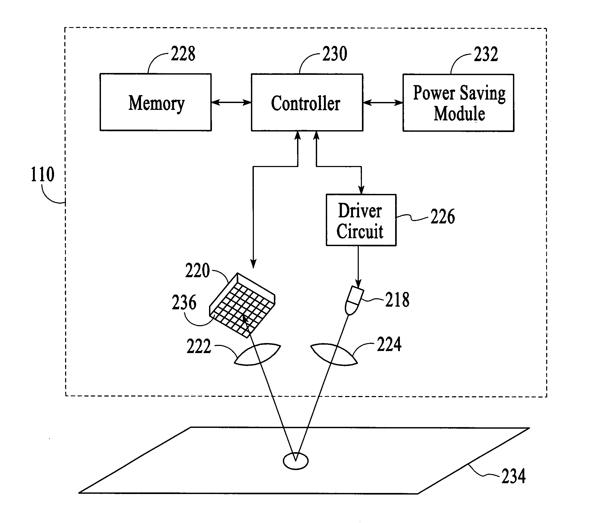
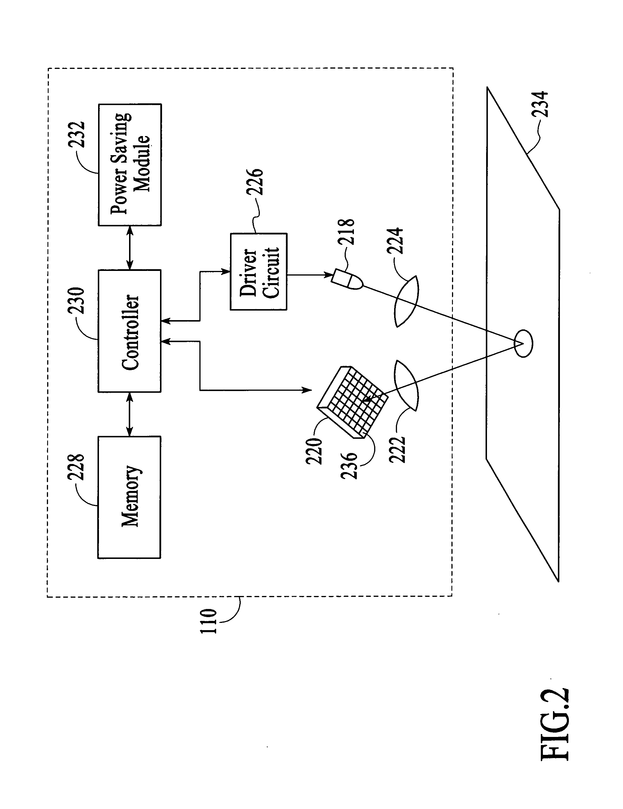
[0007] An optical navigation system in accordance with an embodiment of the invention comprises an image sensor, a controller and a power saving module. The image sensor includes photosensitive pixel elements and is configured to capture an image frame of a target surface using a predefined number of the photosensitive pixel elements. The controller is operably connected to the image sensor and is configured to control the image sensor for image capture. The controller is further configured to compute a surface quality value of the image frame and to process the image frame to estimate displacement. The power saving module is operably connected to the controller. The power saving module is configured to monitor the surface quality value and to selectively instruct the controller to reduce the predefined number of the photosensitive pixel elements to be used to capture a subsequent image frame of the target surface based on a comparison of the surface quality value with a threshold value.
[0008] A method for reducing the power consumption of an optical navigation system in accordance with an embodiment of the invention comprises capturing an image frame of a target surface using a predefined number of photosensitive pixel elements, processing the image frame to estimate displacement, including computing a surface quality value of the image frame, comparing the surface quality value with a threshold value, and selectively reducing the predefined number of photosensitive pixel elements to be used to capture a subsequent image frame of the target surface based on the comparing of the surface quality value with the threshold value.
[0009] A method for reducing the power consumption of an optical navigation system in accordance with an embodiment of the invention comprises capturing an image frame of a target surface using a predefined photosensitive is pixel array, processing the image frame to estimate displacement, including computing a surface quality value of the image frame, comparing the surface quality value with a threshold value, and selectively reducing the said predefined photosensitive pixel array to be used to capture a subsequent image frame of the target surface based on the comparing of the surface quality value with the threshold value.

Problems solved by technology

However, using these techniques, no power saving is achieved when the optical mouse is in motion.
However, these power reducing techniques tend to significantly compromise the tracking performance of the optical navigation system.

Method used


Image

  • Optical navigation system and method for reducing the power consumption of the system
  • Optical navigation system and method for reducing the power consumption of the system
  • Optical navigation system and method for reducing the power consumption of the system

Examples


Embodiment Construction

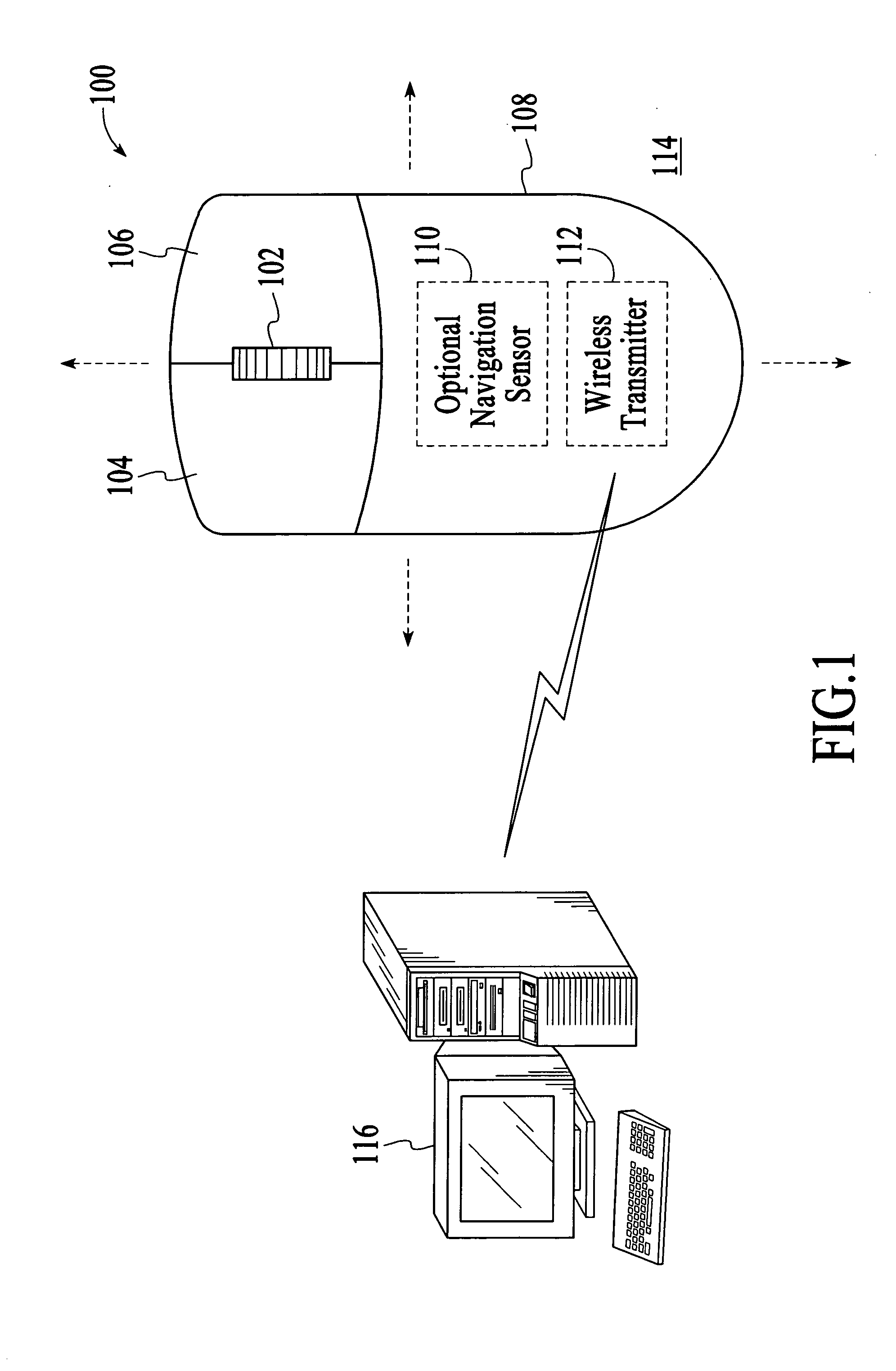
[0015] With reference to FIG. 1, a cordless optical computer mouse 100 in accordance with an embodiment of the invention is described. As shown in FIG. 1, the optical mouse 100 includes a wheel 102, buttons 104 and 106, and a housing 108 onto which the wheel and the buttons are attached. The optical mouse 100 also includes an optical navigation system 110 and a wireless transmitter 112. The optical mouse 100 is a wireless input device that tracks movements of the mouse relative to a target surface 114 on which the mouse is manually manipulated. The optical navigation system 110 operates to successively capture image frames of the target surface 114, which are compared to estimate the relative movements between the optical mouse 100 and the target surface 114. The estimated relative movements are output as tracking information, which includes two dimensional displacement data, i.e., Δx and Δy data. The tracking information is then transmitted to an associated computer 116 via the wir...


PUM


Abstract

An optical navigation system and method for reducing the power consumption of the system uses a surface quality value of a captured image frame of a target surface to selectively reduce the number of photosensitive pixel elements to be used to capture a subsequent image frame.

Description

BACKGROUND OF THE INVENTION [0001] Optical navigation systems detect relative movements between the optical navigation systems and target surfaces to perform tracking operations. An optical navigation system uses a light source, such as a light-emitting diode or a laser diode, and an image sensor to successively capture image frames of a target surface. The optical navigation system compares the successive image frames and estimates the relative movements between the optical navigation system and the target surface based on the comparison between the current image frame and a previous image frame. The optical navigation system is able to track the relative movements between the optical navigation system and the target surface by continuously capturing and comparing image frames. [0002] Optical navigation systems are commonly used in optical computer mice to track the movements of the mice relative to the surfaces on which the mice are manually manipulated. An optical computer mouse ...

Claims


Application Information

Patent Timeline
IPC IPC(8): H01J40/14G01J1/44H03F3/08
CPCG06F3/0317G06F1/3215
Inventor CHEAH, CHIANG SUNTAI, LI CHONGBROSNAN, MICHAEL J.
Owner PIXART IMAGING INC
Learn More