Tape reel, method of and apparatus for attaching tape to reel hub and method of and apparatus for winding tape on tape reel

Inactive Publication Date: 2007-11-15
FUJIFILM CORP
View PDF8 Cites 6 Cited by
  • Summary
  • Abstract
  • Description
  • Claims
  • Application Information

AI Technical Summary

Benefits of technology

[0009] According to the tape reel since the reel hub has pores for air intercommunication between the interior and the exterior of the center bore of the reel hub, it is realized to attach an end portion of tape strip to the reel hub without using a sticking liquid at the beginning of winding of the tape strip on the tape reel. Nonuse of sticking liquid eliminates an occurrence of defects in attaching a tape end to the tape reel and provides stable quality of tape end attaching to the reel hub and, since a product of porous material has intrinsic pores distributed uniformly allover the product, the reel hub is capable of making an end portion of tape strip to attach uniformly thereto. In consequence, the tape reel prevents an occurrence of a radial irregularity in a roll of tape strip wound on the reel hub.
[0011] According to the tape end attaching method, since an end portion of tape strip grasped by the tape carrier is attached to the reel hub without using a sticking liquid, no defect takes place in attaching a tape end to the tape reel and stable quality of tape end attaching is provided.
[0012] The tape cartridge is manufactured by winding a tape on the tape reel after attaching a tape end of the tape to the reel hub of the tape reel by the tape end attaching method. Accordingly, it is realized to provide a tape cartridge with a roll of tape wound on the tape reel superior in terms of winding quality.

Problems solved by technology

A problem encountered by the tape end sticking apparatus is an occurrence of defects in tape end sticking due to excessively large or small spreads of sticking liquid.
Specifically, an excessively large spread f sticking liquid causes the end portion of magnetic tape strip slips relatively to the reel hub and is stuck in an off-center position with respect to the reel hub consequently or fails to stick on the reel hub.
In some cases, a redundant spread of sticking liquid runs off from between the tape end portion and the reel hub and is left as adhesion vestiges on flanges which are undesirable in appearance.
On the other hand, an excessively small spread of sticking liquid fails in unsuccessful sticking of the tape end portion on the reel hub and, in particular, accounts for a turnup or a bend of the tape end portion.

Method used


Image

  • Tape reel, method of and apparatus for attaching tape to reel hub and method of and apparatus for winding tape on tape reel
  • Tape reel, method of and apparatus for attaching tape to reel hub and method of and apparatus for winding tape on tape reel
  • Tape reel, method of and apparatus for attaching tape to reel hub and method of and apparatus for winding tape on tape reel

Examples


Embodiment Construction

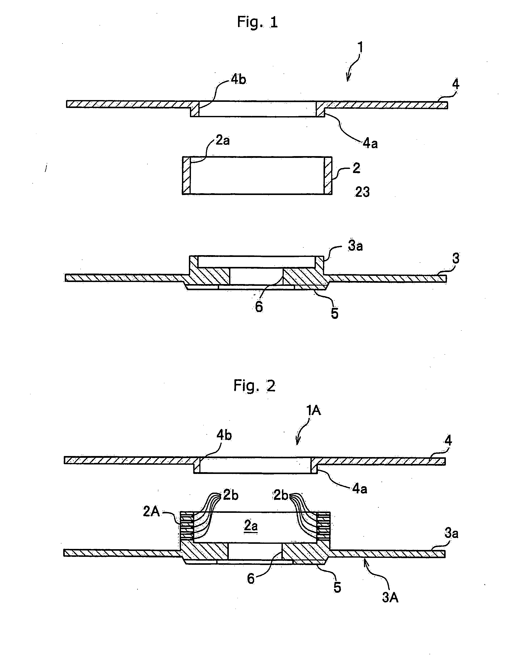
[0028] Referring now to the accompanying drawings in detail FIG. 1 is an exploded sectional view of a tape reel 1 according to an embodiment of the present invention. The tape reel 1 comprises a cylindrical reel hub 2 having a center bore 2a formed axially therein which is made of a porous material such as a porous metal, a porous resin or a porous ceramic material and upper or first and lower or second disk-shaped flanges 3 and 4 which are identical in outer diameter. The reel hub 2 has a number of pores distributed uniformly allover the hub wall which permit air to intercommunicate between the interior and the exterior of the center bore 2a of the reel hub 2. The lower flange 3 has a circular center opening 6 surrounded by a circular boss 3a which extends from the inner surface of the lower flange 3 so as to fit tightly in one of opposite axial end openings of the center bore 2a of the reel hub 2 and has an inner diameter sufficiently grater than the circular center opening 6 and ...


PUM


Abstract

A tape reel on which a tape strip is wound comprises a cylindrical reel hub having pores distributed allover a hub wall and a center bore formed axially therein and flanges connected opposite ends of the reel hub. The interior of the center bore of the reel hub is depressurized so as thereby to attach an end portion of a tape strip to the reel hub with air sucked in through the pores.

Description

BACKGROUND OF THE INVENTION [0001] 1. Field of the Invention [0002] The present invention relates to a tape reel, a tape cartridge and a method of attaching a magnetic tape strip to a reel hub of the tape reel. [0003] 2. Description of Related Art [0004] Typically, data storage magnetic tape cartridges are commonly used as an external memory device for computer data backup. Such a tape cartridge comprises a cartridge case, a tape reel and its associated parts enclosed in the cartridge case. Generally, the tape reel comprises a cylindrical core formed as a reel hub on which a tape strip is wound and upper and lower flanges radially extending at opposing ends of the reel hub. In a tape cartridge manufacturing line, tape winding is entered by firmly attaching one end of the magnetic tape strip to the reel hub using a tape end sticking apparatus There have been proposed a variety of tape end sticking apparatuses. One of the tape end sticking apparatuses which is known from, for example,...

Claims


Application Information

Patent Timeline
IPC IPC(8): B65H19/28B65H75/28G11B23/107
CPCB65H75/28G11B23/113G11B23/107B65H2701/378
Inventor KUBOTA, KAZUO
Owner FUJIFILM CORP
Why Eureka
Try Eureka