Miniaturized gas refrigeration device with two or more thermal regenerator sections

a refrigeration device and thermal energy exchange technology, applied in the direction of gas cycle refrigeration machines, refrigeration machines, lighting and heating apparatus, etc., can solve the problem that the refrigerator module does not provide a 100% thermal energy exchange with the refrigeration gas, and achieve the effect of high resistance to thermal energy conduction

Inactive Publication Date: 2007-11-15
TELEDYNE FLIR LLC
View PDF48 Cites 9 Cited by
  • Summary
  • Abstract
  • Description
  • Claims
  • Application Information

AI Technical Summary

Benefits of technology

[0019] In one example a first regenerator module (R) is disposed in a regenerator portion of a movable gas displacing piston (138) and a second regenerator module (R1) is disposed in a fluid control unit (152) of the movable gas displacing element (138). Cold refrigeration gas enters the first regenerator module (R) from an expansion space (142) and cools a thermal regenerator substrate contained therein. However, the first regenerator module does not provide a 100% thermal energy exchange with the refrigeration gas.
[0020] A thermal barrier (T) is disposed between the first regenerator module (R) and the second regenerator module (R1). The thermal barrier T includes insulating elements disposed to create a high resistance to thermal energy conduction between the first regenerator module (R) and the second regenerator module (R1). Refrigerati

Problems solved by technology

However, the first regenerator module does not provide a 100% thermal energy exchange with the refrigeration gas.

Method used


Image

  • Miniaturized gas refrigeration device with two or more thermal regenerator sections
  • Miniaturized gas refrigeration device with two or more thermal regenerator sections
  • Miniaturized gas refrigeration device with two or more thermal regenerator sections

Examples


Embodiment Construction

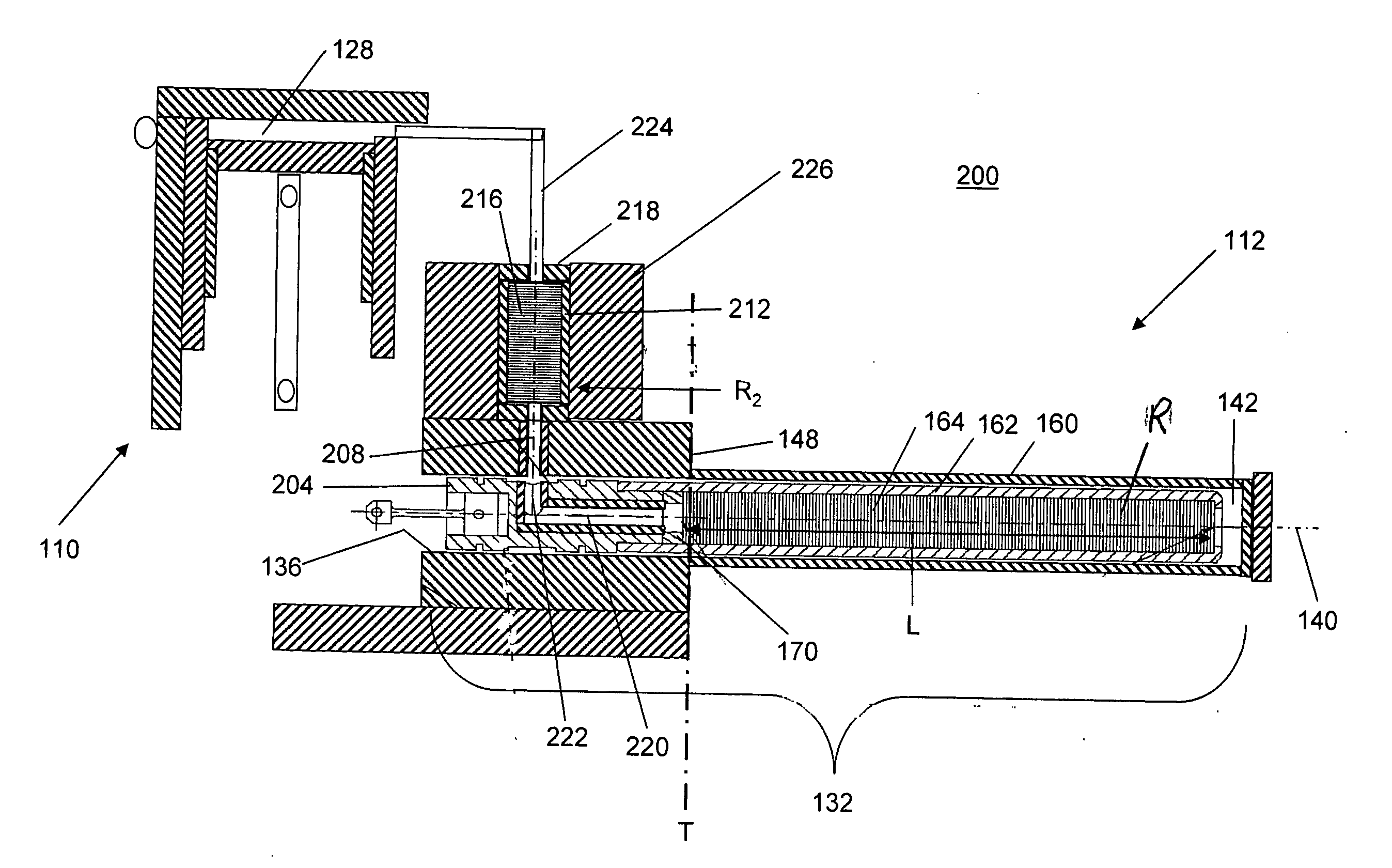
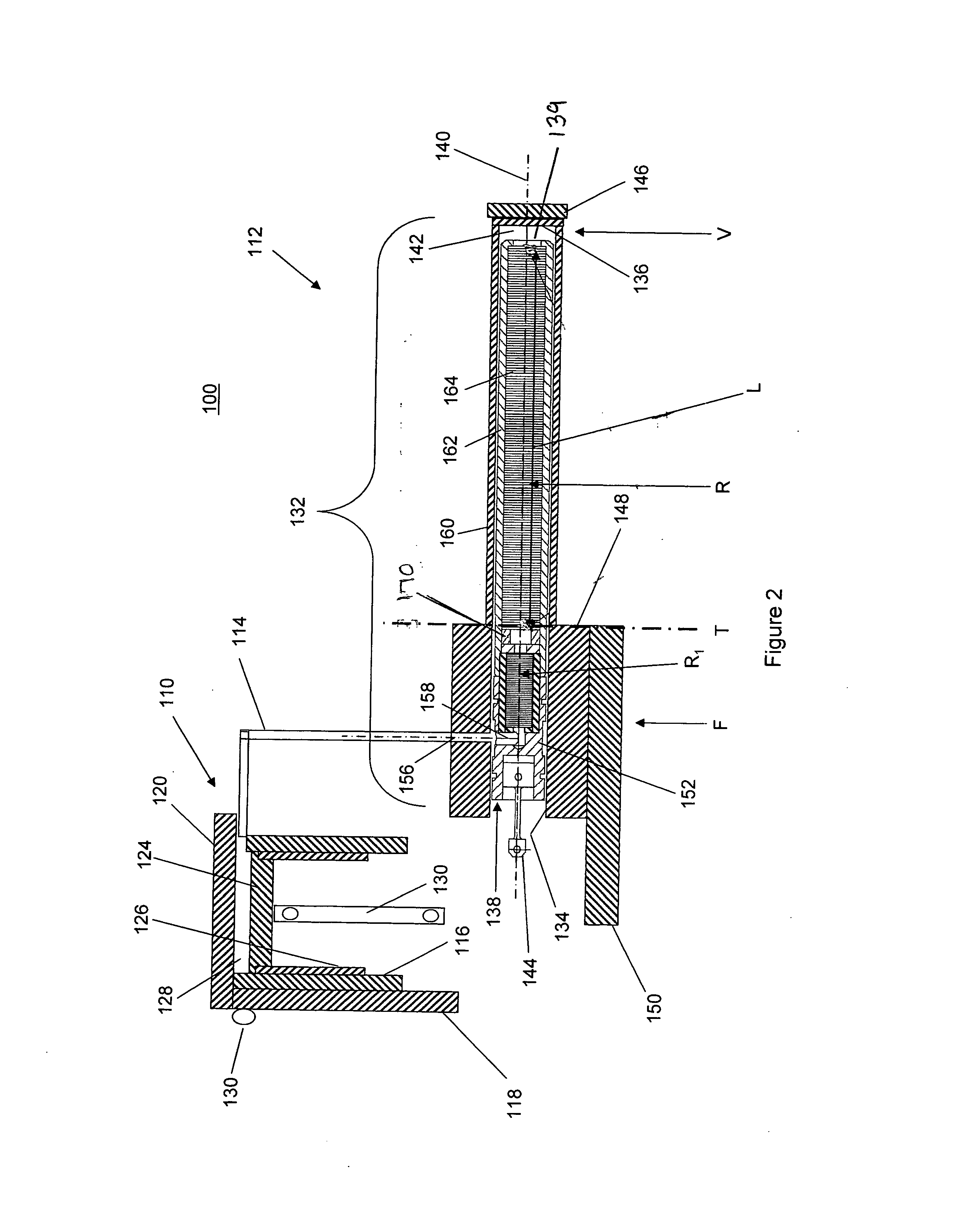
[0030]FIG. 2, depicts a section view taken through portions of a preferred embodiment of an improved refrigeration device 100 according to the present invention. The device 100 includes a sealed working volume filled with a working refrigeration fluid such as helium gas; however, other working fluids are usable. In particular, the refrigeration device 100 includes a gas compression unit 110 and a gas volume expansion unit 112. The compression unit 110 and volume expansion unit 112 are fluidly interconnected by a first fluid conduit 114, and the combined internal volume of these elements forms the working volume. The device 100 is constructed to establish a thermal barrier T which substantially blocks thermal conduction from crossing the dashed line shown in FIG. 2 to demark an approximate boundary between a warm side of the device shown on the left in FIG. 2 and a cold side of the device, shown on the right in FIG. 2. During operation, elements on warm side of the thermal barrier T ...


PUM


Abstract

The size of a miniature cryocooler (100) operating on the Stirling refrigeration cycle is further reduced by shortening a first thermal regenerator module (R) disposed on a cold side of a thermal barrier (T) and providing a second thermal regenerator module (R1) disposed on a warm side of the thermal barrier (T). A thermally insulted fluid flow passage (172) is disposed to interconnect the first and second regenerator modules to thermally insulate the fluid passage (172). In combination, the first and second regenerator modules provide 100% thermal regenerator effectiveness in the device.

Description

CROSS REFERENCE TO RELATED APPLICATIONS [0001] The present invention is related to co-pending and co-assigned U.S. patent applications Ser. No. ______, entitled CABLE DRIVE MECHANISM FOR SELF-TUNING REFRIGERATION GAS EXPANDER, by Uri Bin-Nun filed even dated herewith; [0002] Ser. No. ______, entitled COOLED INFRARED SENSOR ASSEMBLY WITH COMPACT CONFIGURATION, by Bin-Nun et al. filed even dated herewith; [0003] Ser. No. ______, entitled FOLDED CRYOCOOLER DESIGN, by Bin-Nun et al. filed even dated herewith; the entirety of each of which is incorporated herein by reference.BACKGROUND OF THE INVENTION [0004] 1. Field of the Invention [0005] The invention provides an improved refrigeration device. In particular, the improved refrigeration device includes one or more thermal regenerator for exchanging thermal energy with a refrigeration gas with at least one of the thermal regenerator disposed distal from the cold end of the device. [0006] 2. Description of Related Art [0007] A cryogenic...

Claims


Application Information

Patent Timeline
IPC IPC(8): F25B9/00
CPCF25B2309/003F25B9/14F25B2309/1428
Inventor NUN, URI BIN
Owner TELEDYNE FLIR LLC
Why Eureka
Try Eureka