
Traps for crabs or lobsters

a technology for lobsters and crabs, applied in the field of crab or lobster traps, can solve the problems of reducing the catch of crabbers, catching and retaining undersized crabs, and the difficulty of lifting the crab trap presently in us

Inactive Publication Date: 2007-11-15
DECEMBER JOHN
View PDF19 Cites 21 Cited by
  • Summary
  • Abstract
  • Description
  • Claims
  • Application Information

AI Technical Summary

Benefits of technology

[0009] It is accordingly an object of the present invention to provide a novel and improved trap for crabs or lobsters which at least partly mitigates at least one of these problems.
[0011] a mesh extending over the trap frame; at least one inlet opening; a one-way inlet gate at the opening, the one-way inlet gate comprising a plurality of spaced apart pins which are pivotable between open and closed positions; and pin retainers preventing spreading of the pins apart from one another when the pins are in the closed position.
[0012] The provision of the pin retainers prevents the pins from being spread apart from one another by crabs or lobsters attempting to escape from the trap and thereby prevents the crabs or lobsters from being able to move outwardly through the inlet opening.
[0017] These finger openings facilitate grasping and lifting of the trap by the user of the trap.

Problems solved by technology

However, in practice an undesirably large number of crabs, having entered the traps, are able to escape through the crab inlet openings, thereby substantially reducing the crabbers catch.
Another problem of conventional crab traps is that they catch and retain undersized crabs, which should preferably be allowed to escape from the traps.
Also, crab traps presently in use are difficult to lift be hand, because the crabbers fingers are unable to effectively penetrate the mesh so as to engage the crab trap frames.

Method used


Image

  • Traps for crabs or lobsters
  • Traps for crabs or lobsters
  • Traps for crabs or lobsters

Examples


Embodiment Construction

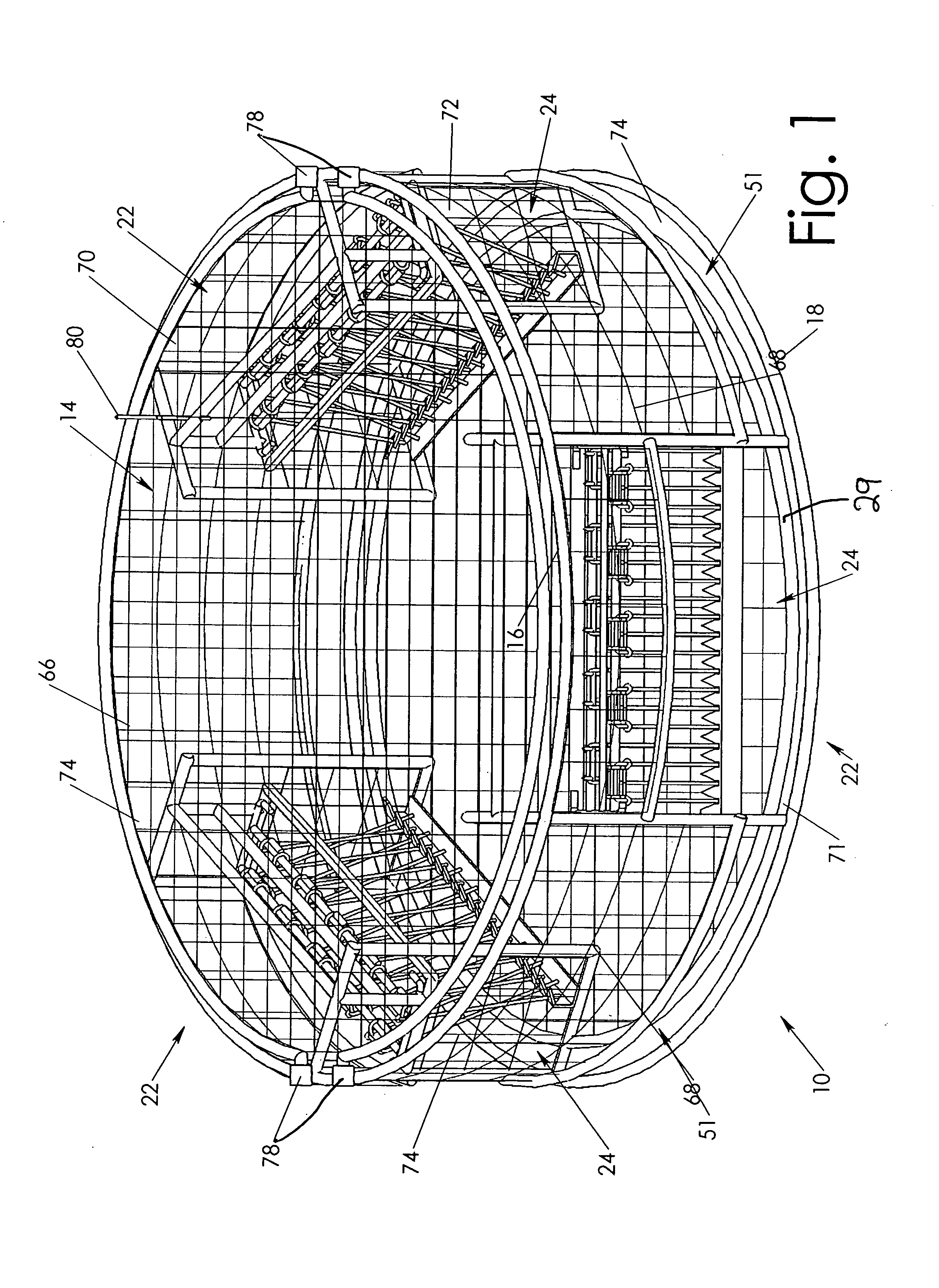
[0025] In FIG. 1 of the accompanying drawings, there is shown a crab trap, indicated generally by reference numeral 10, according to a preferred embodiment of the present invention. The crab trap 10 has a crab trap frame which is indicated generally be reference numeral 12 in FIG. 2 and which, as shown in FIG. 1, is almost entirely covered by a mesh indicated generally by reference numeral 14. The crab trap frame 12 is made of steel rod and the mesh 14 is made of galvanized wire or twine. The mesh 14 has been omitted from FIG. 2 to facilitate illustration of the crab trap frame 12.

[0026] As can be seen from FIGS. 1 and 2, the crab trap 10 is of circular shape, when viewed from above, and the crab trap frame 12 has circular top and bottom peripheral frame portions 16 and 18, which are interconnected by vertical frame members 20.

[0027] The crab trap 10 has three horizontally elongate rectangular crab inlet openings indicated generally by reference numerals 22, which are each provide...


PUM


Abstract

A trap for crabs or lobsters has a mesh extending over a trap frame, with at least one inlet opening provided with a one-way inlet gate spaced apart pins which are pivotable between open and closed positions. Pin retainers prevent spreading of the pins apart from one another when the pins are in the closed position and an undersized crab outlet opening, dimensioned to allow undersized crab or lobsters to escape from the interior chamber, is provided at a side of the trap and at the bottom of the trap. The frame includes an top peripheral frame portion and finger grip openings at the underside of the trap frame. The one-way inlet gate has first and second sets of spaced apart pins, each set being pivotable independently of the other between open and closed positions. Also, the one-way inlet gate has pairs of pins which are pivotable between the open and closed positions, each pair being formed by parallel legs of a U-shaped length of wire, with retainers engaging the legs of each pair to prevent spreading of the legs.

Description

BACKGROUND OF THE INVENTION [0001] 1. Field of the Invention [0002] The present invention relates to traps for crabs or lobsters and comprising a mesh of rope or other material provided on a trap frame. [0003] 2. Description of the Related Art [0004] Crab traps in use at the present time have hollow interiors within crab trap frames, with wire meshes extending around the frame to enclose a hollow interior and with crab inlet openings in the meshes and the frames, through which crabs can crawl into the interiors of the crab frames when the crab traps are in use. [0005] In order to prevent the crabs from leaving the interiors of the crab traps, the crab inlet openings have been shaped as conical openings spaced upwardly from the bottoms of the traps and tapering inwardly of the traps so as to make it difficult for the crabs to find their way out from the traps. Also, the crab inlet openings have been provided with one-way gates, which open inwardly to allow the crabs to enter. These o...

Claims


Application Information

Patent Timeline
IPC IPC(8): A01K69/08A01K69/06
CPCA01K69/06
Inventor DECEMBER, JOHN
Owner DECEMBER JOHN
Learn More