
Apparatus for tilting away a part of a signature to be separated from a rack

a technology of a rack and a signature, which is applied in the direction of article separation, pile separation, thin material handling, etc., can solve the problem of not always being vaccinated, and achieve the effect of simple manner

Inactive Publication Date: 2007-11-08
WOHLENBERG BUCHBINDESYST
View PDF14 Cites 0 Cited by
  • Summary
  • Abstract
  • Description
  • Claims
  • Application Information

AI Technical Summary

Benefits of technology

[0006]The invention is based on the object of providing an apparatus for tilting away a corner or a strip of a signature to be separated, it being possible to load the sucker of the said apparatus with a vacuum in a simple manner.
[0009]According to one development of the invention, there is provision for the or each vacuum generator to be supplied with compressed air, the amount and / or the pressure of which can be changed. In this way, the intensity of the vacuum can be changed. The vacuum which is present at the sucker can therefore be adapted to the requirements by being increased or reduced. The negative pressure at the sucker can be changed in a simple manner by a change in the compressed-air supply of the at least one vacuum generator by means of an adjusting throttle in the compressed-air supply line which leads to the vacuum generator or a plurality of valves which can be actuated individually in the compressed-air supply line. The compressed-air supply to the at least one vacuum generator can be changed in stages by opening all or only certain valves. The valves preferably have different cross sections for the passage of compressed air. Precisely graduated amounts of compressed air for supplying the or each vacuum generator can be set individually by targeted opening of a defined valve or a plurality of defined valves.
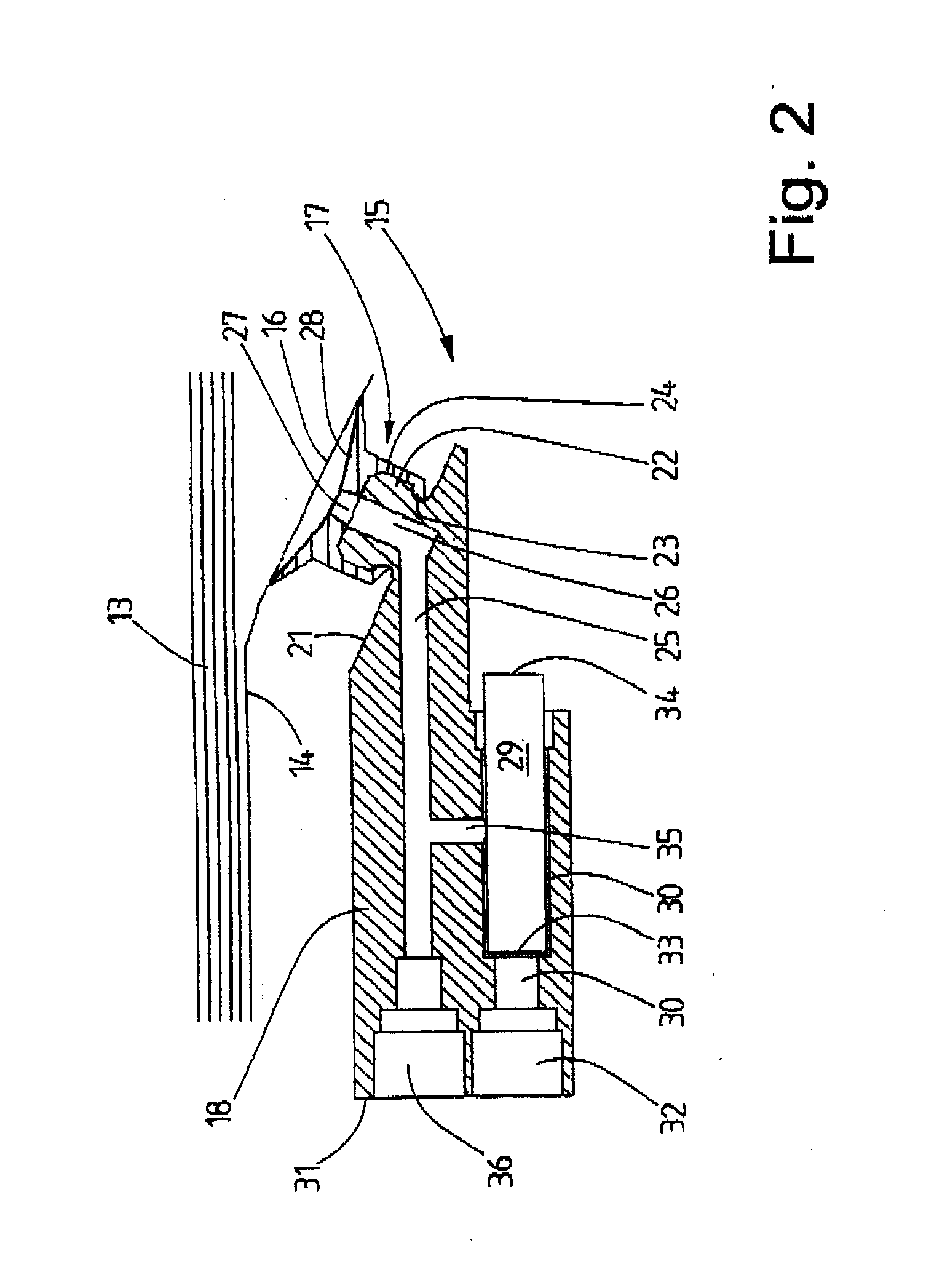
[0010]The vacuum generator is preferably provided on or in the carrier. The vacuum generator, that is to say the location, at which the vacuum is generated, is situated as a result in the vicinity of the sucker, at which the vacuum is required. In this way, the invention permits the shortest possible supply lines between the vacuum generator and the sucker. Only a relatively small amount therefore has to be evacuated, in order to generate a vacuum at the sucker. In known apparatuses of this type, the relatively long supply lines have a large internal volume which requires a great amount of air to be sucked away, until the long supply line is evacuated and a vacuum is available at the sucker. This has the consequence of high energy consumption and is also noise-intensive.
[0013]In particular, a vacuum pump which operates according to the ejector principle or the multiple-stage ejector principle is particularly compact and can therefore be arranged, according to one preferred refinement of the invention, in a receptacle in the carrier, which receptacle is configured as a simple blind hole or through hole. As a result, it is possible to accommodate the vacuum pump in the carrier in a particularly space-saving manner and the vacuum pump can be placed as closely as possible to the sucker in this way, above all, as a result of which only a short supply line having a low volume is required, with the result that only a small amount of air is to be evacuated out of the supply line in order to generate a vacuum at the sucker and, accordingly, only a relatively small amount of compressed air has to be used in order to generate the vacuum which is required for attracting by suction a part of a signature to be separated.
[0014]According to one preferred development of the invention, there is provision for it to be possible also to load the respective sucker with compressed air from time to time, in particular for a short period. As a result, rinsing and, in the process, cleaning of the supply channel, but also of the sucker, takes place. At the same time, the signature is separated from the sucker, which can be required if the surface of the signature still has slightly adhesive properties. Paper dust and / or release agent can also be eliminated by the cleaning of the sucker, before they can block the sucker or the supply channel which leads to it in an operational interruption.
[0017]One development of the method provides for a vacuum flow from compressed air to be accommodated within the tilting sucker, namely a carrier for the respective sucker which serves as a housing. In this way, the vacuum can be generated in the immediate vicinity of the sucker, as a result of which only an extremely short supply channel is required for loading the sucker with vacuum, which supply channel can be evacuated quickly on account of its shortness, as a result of which the vacuum consumption can be reduced considerably by the method according to the invention, in comparison with known tilting suckers.

Problems solved by technology

While compressed air is available everywhere, vacuum is not always present.

Method used


Image

  • Apparatus for tilting away a part of a signature to be separated from a rack
  • Apparatus for tilting away a part of a signature to be separated from a rack
  • Apparatus for tilting away a part of a signature to be separated from a rack

Examples


Embodiment Construction

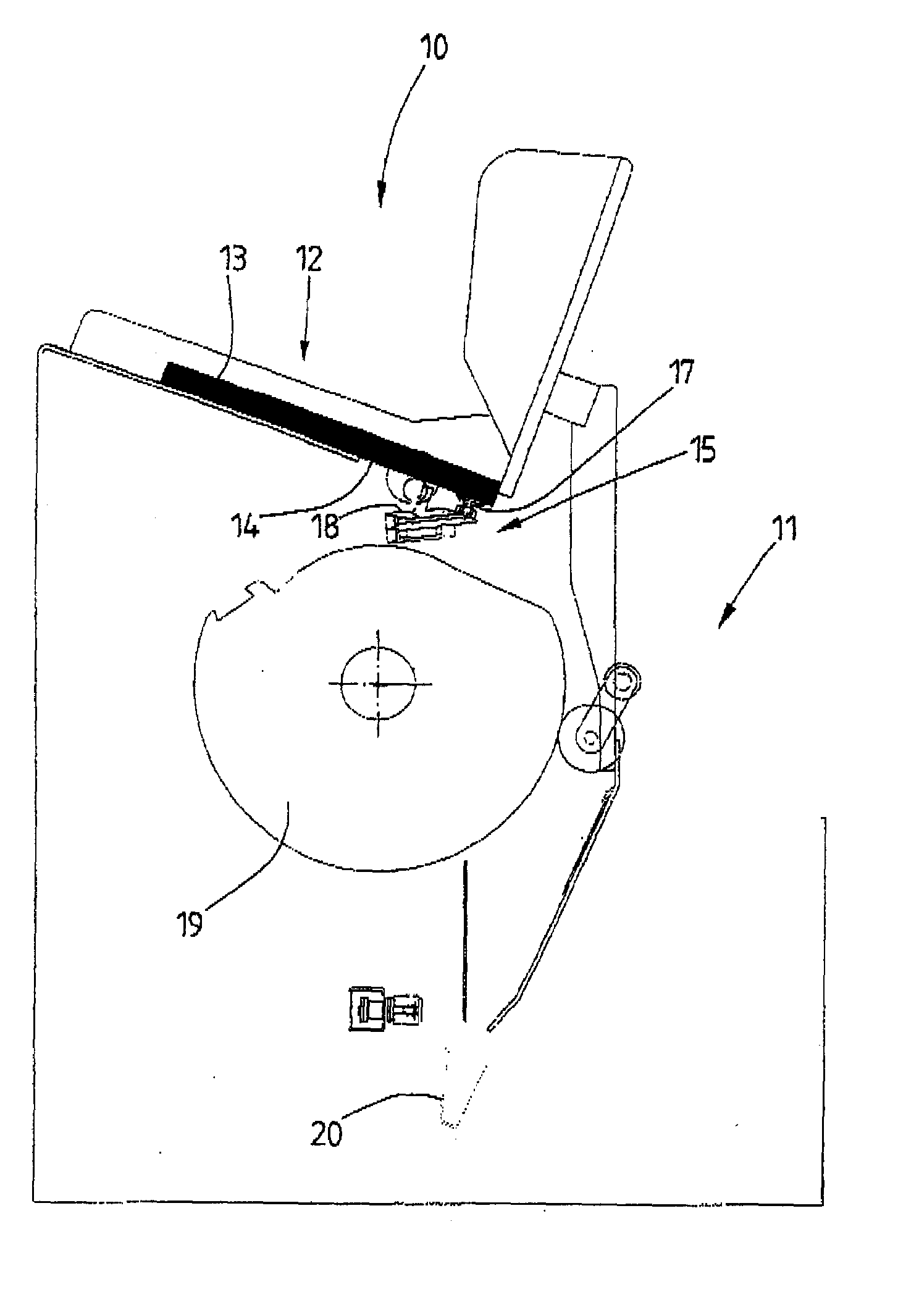
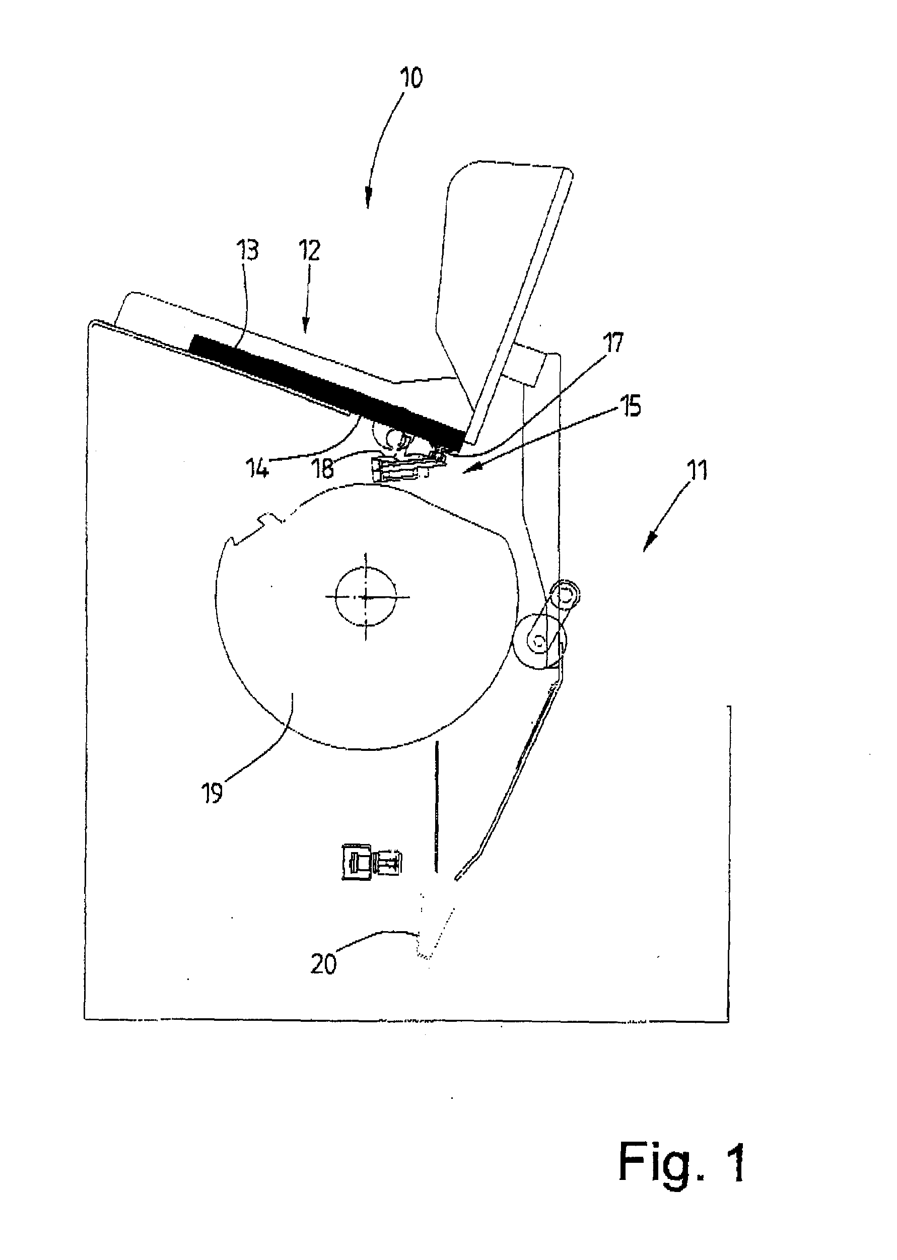
[0022]The invention relates to the field of print further processing. Here, these are devices such as collating machines, adhesive binders or cover feeders. FIG. 1 shows a part of a collating machine 10 in simplified form, namely only one feed station 11 of the collating machine 10 is shown. The feed station 11 has a magazine 12 for accommodating a stack 13 of signatures which lie one above the other, which are folded sheets 14 in the present case. The folded sheets 14 of the stack 13 are separated in the region of the feed station 11, by a lowermost folded sheet 14 being pulled off from under the magazine 12 gradually.

[0023]The respectively lowermost folded sheet 14 of the stack 13 is separated in a first step by the apparatus according to the invention which is configured as a tilting sucker 15 in the collating machine 10 which is shown here. An edge region 16 (it also being possible for it to be only a corner region) of the lowermost folded sheet 14 is tilted away from the stack ...


PUM


Abstract

An apparatus for tilting away a part of a sheet to be separated, in which apparatus a compressed-air supply is sufficient for operating the tilting sucker. To this end, the tilting sucker of the apparatus is assigned a vacuum generator which can be fed with compressed air and which generates a vacuum from the supplied compressed air.

Description

BACKGROUND OF THE INVENTION[0001]1. Technical Field[0002]The invention relates to an apparatus for tilting away a part of a signature to be separated from a stack, having at least one sucker which is arranged on a carrier and can be moved, preferably pivoted, by the carrier for tilting away a part of the signature to be separated, and having at least one supply channel in the carrier for supplying the respective sucker with vacuum.[0003]2. Prior Art[0004]In the print further processing of signatures such as individual sheets, covers or quires, individual signatures are to be pulled off from a stack of signatures. In the separation of the signatures which occurs in this way, first of all a part of the signature to be separated, in particular an edge strip or a corner region, is tilted away with respect to the stack. An apparatus of the type which is addressed here serves for this purpose, which apparatus is also known briefly as a tilting sucker in the specialist language.[0005]An ap...

Claims


Application Information

Patent Timeline
IPC IPC(8): B65H3/08
CPCB65H3/0858B65H3/0891B65H2406/3661B65H2406/341B65H2406/365B65H3/14
Inventor BRORKEN, JUTTA R.
Owner WOHLENBERG BUCHBINDESYST
Learn More