
Cryopump and regenerating method of the cryopump

a cryopump and regenerating technology, applied in the direction of positive displacement liquid engines, separation processes, lighting and heating apparatus, etc., can solve the problems of inability to control the rising temperature of the first and second stages of the cooling stage b>7/b> independently, the rotational speed cannot be frequently changed, and the regenerating process takes a long tim

Active Publication Date: 2007-11-08
SUMITOMO HEAVY IND LTD
View PDF8 Cites 28 Cited by
  • Summary
  • Abstract
  • Description
  • Claims
  • Application Information

AI Technical Summary

Benefits of technology

[0055]Accordingly, embodiments of the present invention may provide a novel and useful cryopump and regenerating method of the cryopump in which one or more of the problems described above are eliminated.
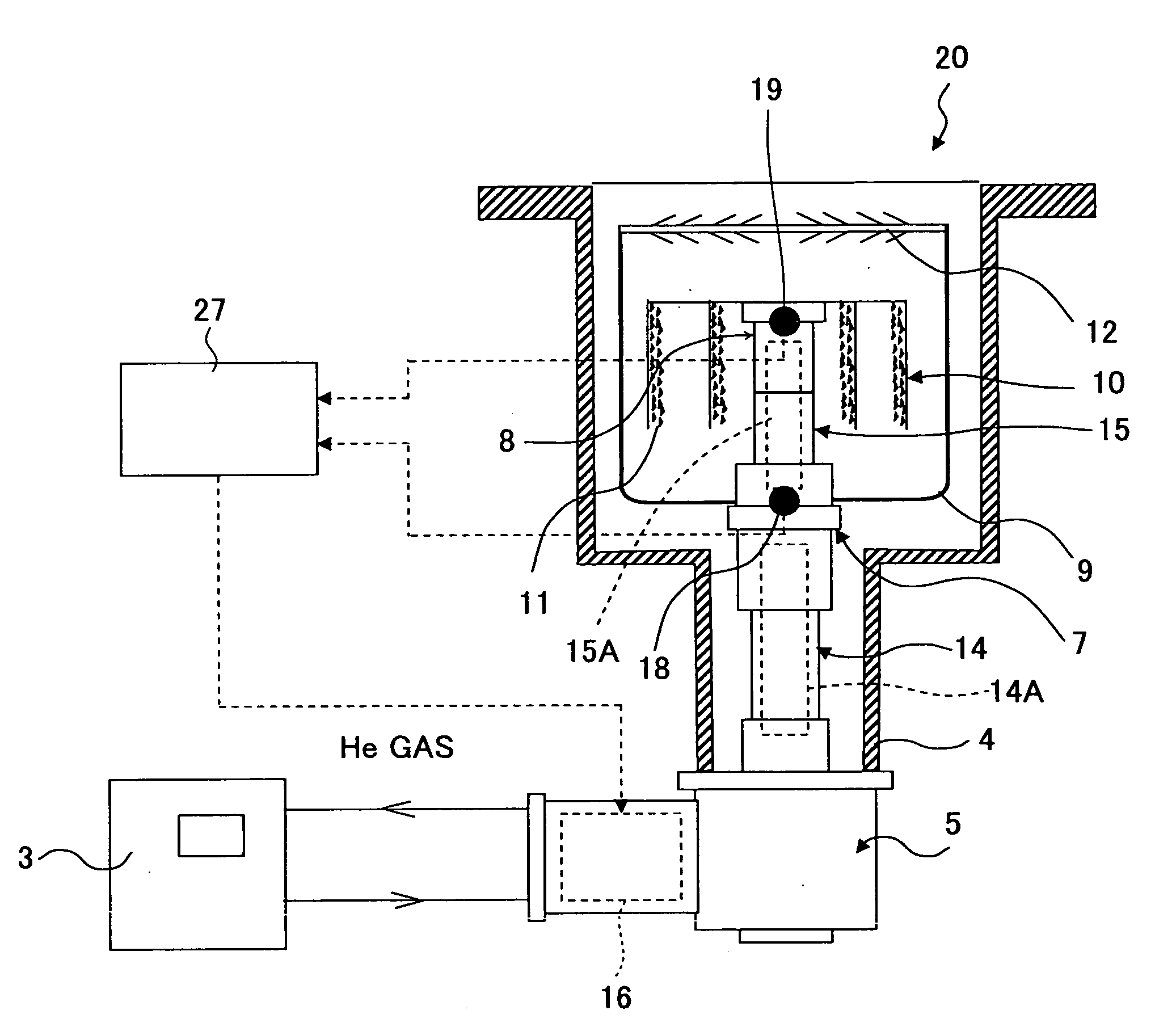
[0056]More specifically, the embodiments of the present invention can provide a cryopump and a regenerating method of the cryopump whereby temperatures of a first stage and a second stage can be securely increased to target temperatures and time required for regenerating can be shortened.
[0068]Therefore, the temperatures of the first stage cooling stage and the second stage cooling stage can be securely raised to the target temperatures without frequently changing the rotation speed of the reversible motor.
[0069]Hence, time required for regenerating can be shortened and too much increase of the temperature of the first stage cooling stage can be prevented.
[0083]The heating part is not limited to the reverse rotation of the cryogenic cooler. The heating part may be a heater or the like. This case as well as the case of the reverse rotation of the cryogenic cooler is effective in that reliability of the cryopump can be maintained.

Problems solved by technology

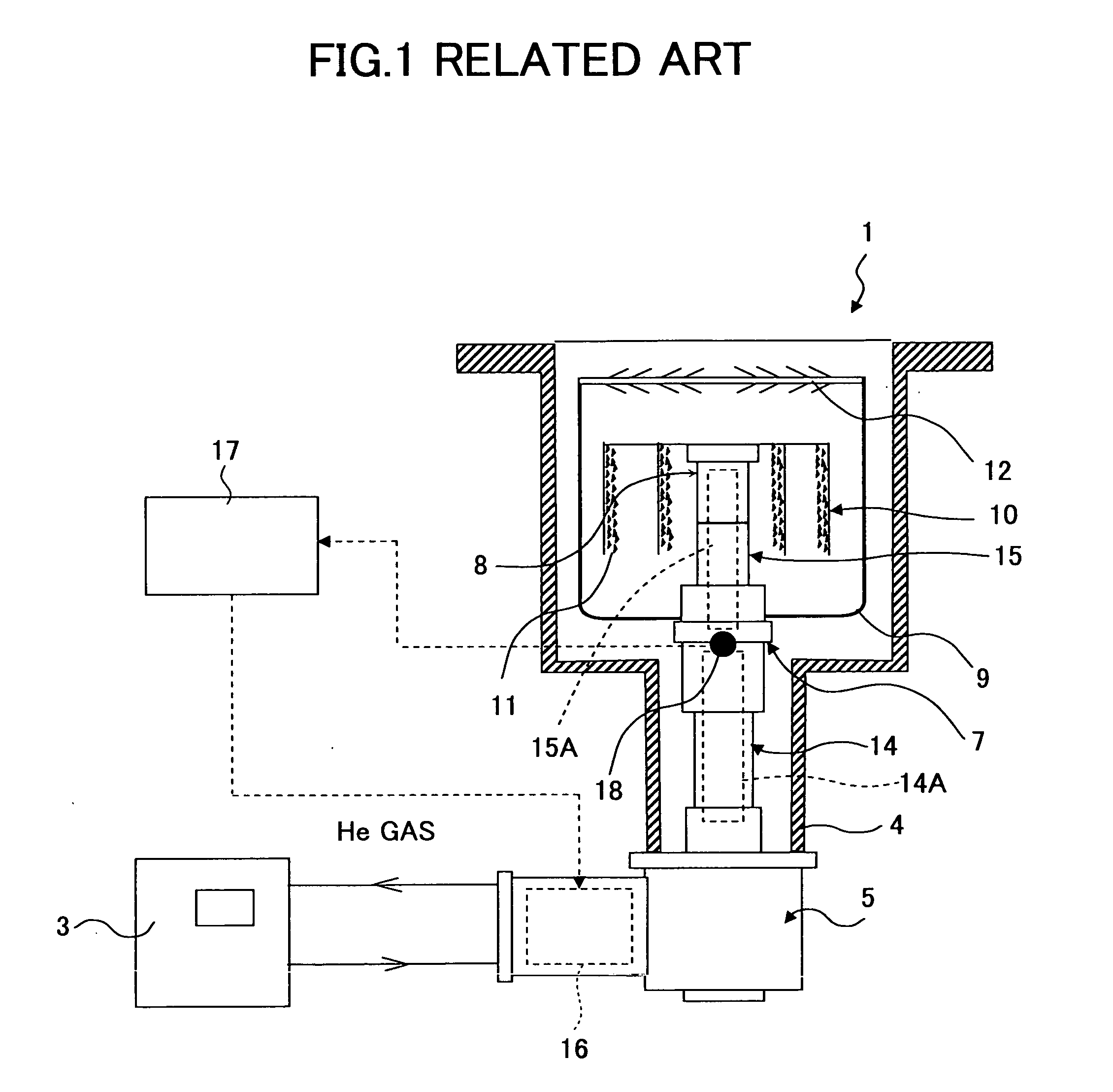
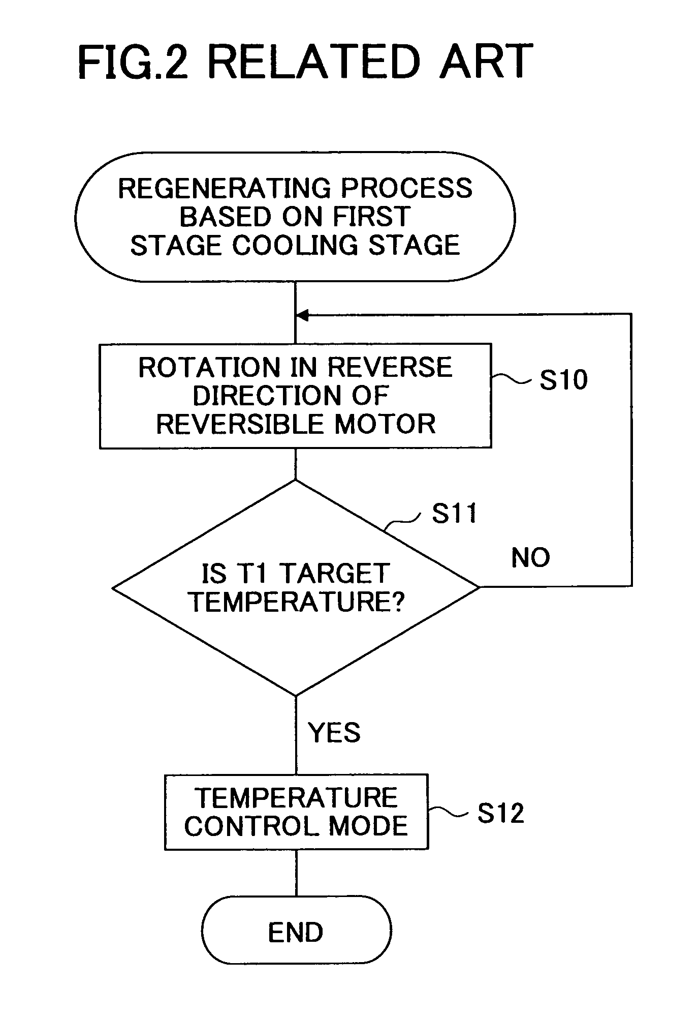
However, in the cryopump 1 where the cooling cycle of the cryogenic cooler is reversed by rotating the reversible motor 16 in the reverse direction so that the regenerating process is implemented, it is not possible to control rising temperatures of the first stage cooling stage 7 and the second stage cooling stage 8 independently.
However, in the actual cryogenic cooler, the rotational speed cannot be frequently changed due to the characteristic of the reversible motor 16.
Hence, in the related art, the regenerating process takes a long time.
Rising temperature continues even after the time t1, so that a problem may occur.

Method used


Image

  • Cryopump and regenerating method of the cryopump
  • Cryopump and regenerating method of the cryopump
  • Cryopump and regenerating method of the cryopump

Examples


status example 1

[0126]In this status, the temperature Tr2 of the second stage cooling stage 8 is lower than the reliability limiting (critical) temperature Stp-t2, namely, Tr22; the temperature Tr1 of the first stage cooling stage 7 is higher than the reliability limiting (critical) temperature Stp-t1, namely, Tr1>Stp-t1; and the reversible motor 16 is being rotated in the reverse direction, namely the temperature rising (heating) process is implemented.

[0127]In this state, in step S21, the controller 27 determines that the cryopump 1 is in the statuses indicated by P3 and P6 in FIG. 7. In addition, since the reversible motor 16 is being rotated in the reverse direction, the controller 27 extracts processes corresponding to P3 and P6 from the bottom section of the process table shown in FIG. 8.

[0128]Thus, the controller 27 determines that the process corresponding to the status example 1 is a process for stopping the rotation of the reversible motor 16.

[0129]Therefore, in the case of the status exa...

status example 2

[0130]In this status, the temperature Tr2 of the second stage cooling stage 8 is lower than the reliability limiting (critical) temperature Stp-t2, namely, Tr22; the temperature Tr1 of the first stage cooling stage 7 is lower than the control returning temperature Rst-t1, namely, Tr11; and the rotation of the reversible motor 16 is stopped because the temperature Tr1 of the first stage cooling stage 7 exceeds the reliability limiting (critical) temperature Stp-t1.

[0131]In this state, in step S21, the controller 27 determines that the cryopump 1 is in the statuses indicated by P1 and P4 in FIG. 7. In addition, since the rotation of the reversible motor 16 is stopped because the temperature Tr1 of the first stage cooling stage 7 exceeds the reliability limiting (critical) temperature Stp-t1, the controller 27 extracts processes corresponding to P1 and P4 from the uppermost section of the process table shown in FIG. 8.

[0132]Thus, the controller 27 determines that the process correspond...

status example 3

[0135]In this status, the temperature Tr1 of the first stage cooling stage 7 is lower than the reliability limiting (critical) temperature Stp-t1, namely, Tr11; the temperature Tr2 of the second stage cooling stage 8 is higher than the reliability limiting (critical) temperature Stp-t2, namely, Tr2>Stp-t2; and the reversible motor 16 is being rotated in the reverse direction, namely the temperature rising process is implemented.

[0136]In this state, in step S21, the controller 27 determines that the cryopump 1 is in the statuses indicated by P7 and P8 in FIG. 7. In addition, since the reversible motor 16 is being rotated in the reverse direction, the controller 27 extracts processes corresponding to P7 and P8 from the bottom section of the process table shown in FIG. 8.

[0137]Thus, the controller 27 determines that the process corresponding to the status example 3 is a process for stopping the rotation of the reversible motor 16.

[0138]Therefore, in the case of the status example 3, th...


PUM

PropertyMeasurementUnit
temperatureaaaaaaaaaa

Abstract

A cryopump and a regenerating method of the cryopump whereby temperatures of a first stage and a second stage can be securely increased to target temperatures and time required for regenerating can be shortened are provided. At the time of regenerating, the temperature of the second stage cooling stage is controlled based on the temperature detected by the second temperature detection part. In the case where the temperature of the first stage cooling stage reaches the limiting temperature, namely critical temperature, of the first stage displacer, the rotation in the reverse direction of the reversible motor is controlled or stopped and thereby the regenerating process is stopped for a while.

Description

BACKGROUND OF THE INVENTION[0001]1. Field of the Invention[0002]The present invention generally relates to cryopumps and regenerating methods of the cryopumps. More particularly, the present invention relates to a cryopump configured to implement a regenerating process by reverse-operating a cryogenic cooler and a regenerating method of the cryopump.[0003]2. Description of the Related Art[0004]In semiconductor manufacturing equipment, for example, it is necessary to realize a high vacuum state. Accordingly, cryopumps are frequently used as vacuum pumps for realizing the high vacuum state. The cryopump requires a cryogenic cooler in the principle of vacuum production. As the cryogenic cooler used for the cryopump, a Gifford McMahon cycle type cryogenic cooler (hereinafter “GM-type cryogenic cooler”) is known.[0005]The GM-type cryogenic cooler and a cryopanel or the like provided in a pump housing are thermally connected to each other. In a cooling process, a gaseous substance in the ...

Claims


Application Information

Patent Timeline
Patent Type & Authority Applications(United States)
IPC IPC(8): B01D8/00
CPCF04B37/085F04B37/08
Inventor FUKUDA, TSUTOMU
Owner SUMITOMO HEAVY IND LTD
Learn More