
Image Processing System and Method, and Terminal and Server Used for the Same

Inactive Publication Date: 2007-11-01
NEC CORP
View PDF16 Cites 291 Cited by
  • Summary
  • Abstract
  • Description
  • Claims
  • Application Information

AI Technical Summary

Benefits of technology

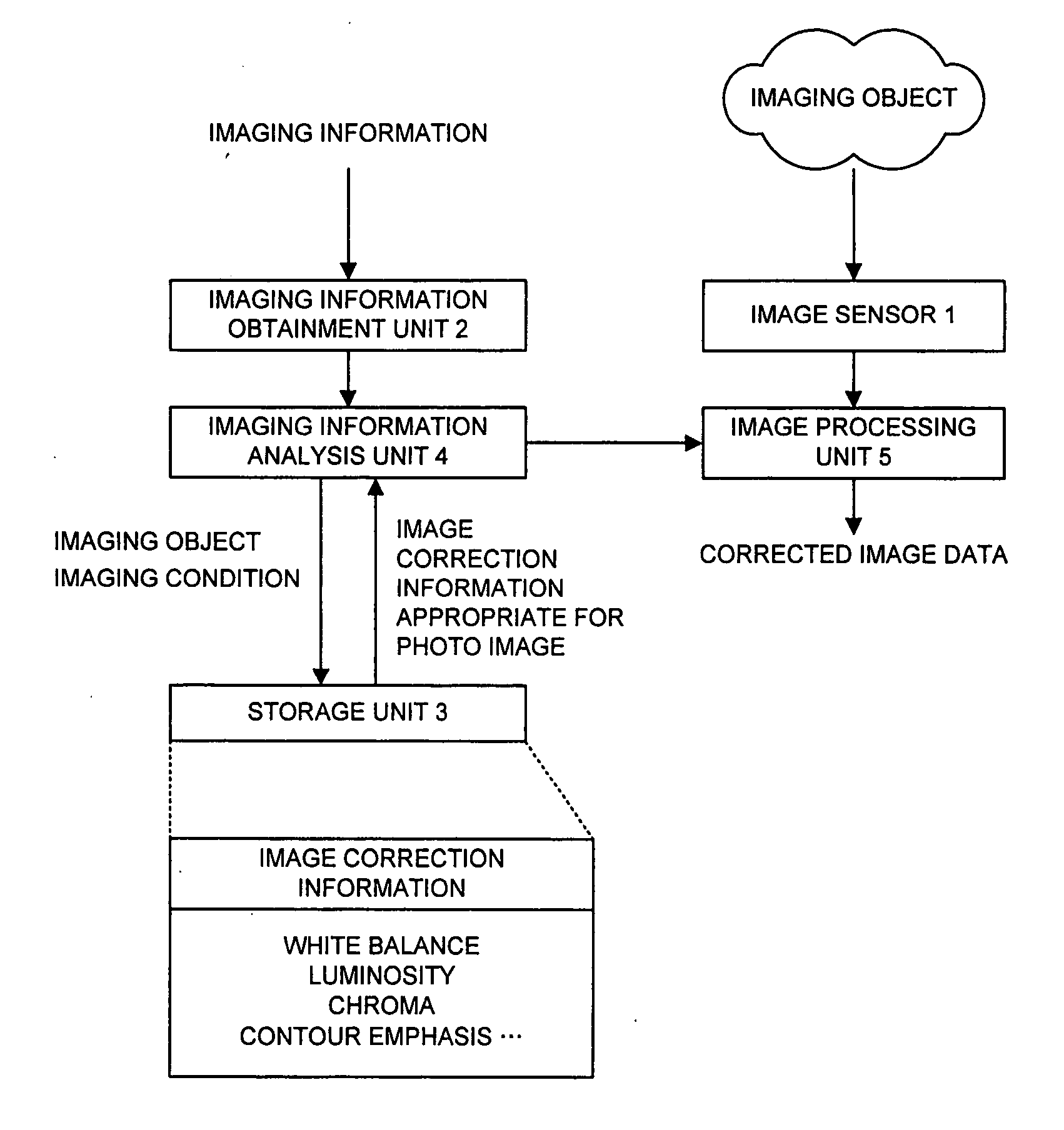
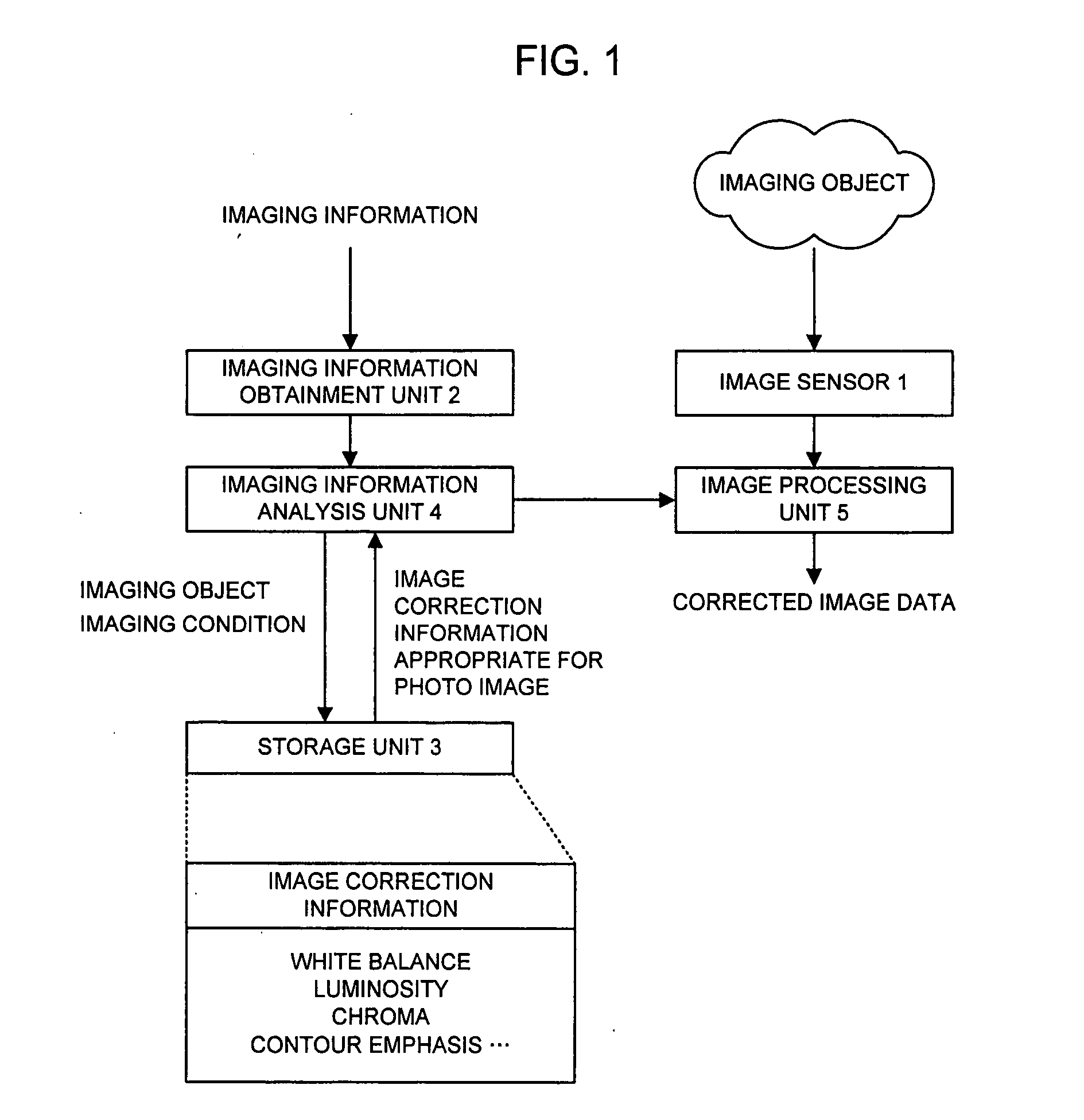
[0039] In accordance with the present invention, imaging information such as location information and date information is obtained, this imaging information is analyzed, and the photo image is subjected to an image correction according to the appropriate image correction information that is obtained based upon an analysis result without causing a photographer to performing a special operation, thereby enabling a person as well, who has no knowledge about the image process, to easily get the photo image that is wonderful.
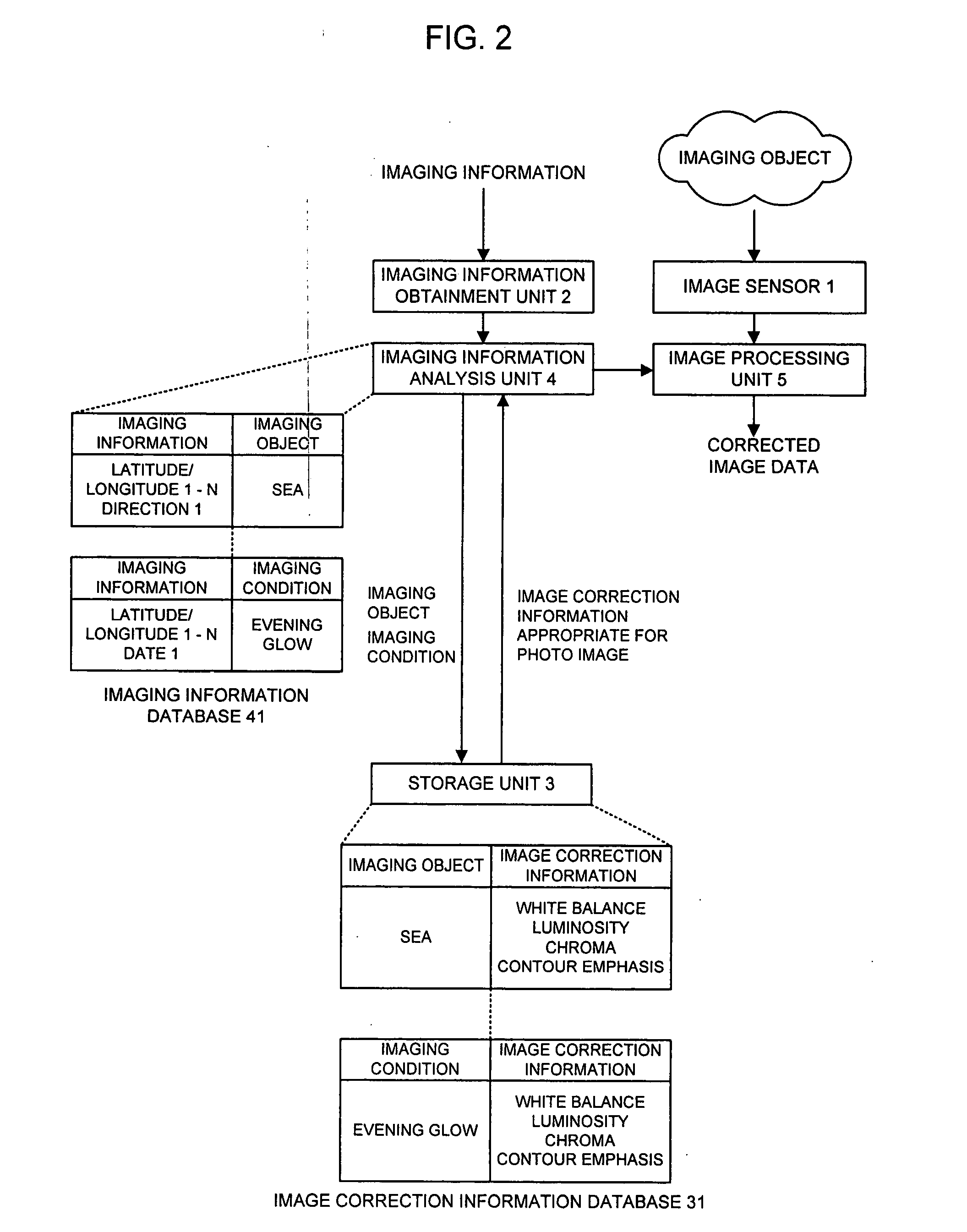
[0040] Further, the present invention, which is configured to analyze the imaging information such as the location information and the date information, thereby to get the imaging object or the imaging condition, and to obtain the image correction information from this imaging object or imaging condition, makes it possible to perform the appropriate correction process for the photo image even in case of the multifarious imaging objects, or the complicated imaging conditions, which is different from the simplified image correction technology of performing an image correction without recognizing a specific imaging object or imaging condition as is the case of the prior art.

Problems solved by technology

However, from a viewpoint of difficulty in setting, a numerous number of the conditions cannot be set to the imaging condition, and only a general-use setting value is prepared for a typical imaging condition, whereby the effect for the actual imaging condition that is multifarious is not so high.
At this time, performing the process necessitates having a medium for performing the process and image processing soft, and in addition, the photo image includes the image that is difficult to correct with inexpensive image processing soft that a general user uses, whereby as a result, the effect of the entire image correction is not so high.
In addition hereto, the image process, and in particular, the correction process of the image necessitates a professional knowledge, which makes it difficult for a general user to perform an appropriate correction process.

Method used


Image

  • Image Processing System and Method, and Terminal and Server Used for the Same
  • Image Processing System and Method, and Terminal and Server Used for the Same
  • Image Processing System and Method, and Terminal and Server Used for the Same

Examples


example 1

[0113] An example 1 of the present invention will be explained.

[0114]FIG. 8 is a view illustrating a configuration of the example 1 of the present invention.

[0115] As shown in FIG. 8, this system is configured of a mobile telephone 100, a server 200, and a network 300 for connecting the mobile telephone 100 and the server 200.

[0116] The mobile telephone 100 includes the foregoing image sensor 1, imaging information obtainment unit 2, and image processing unit 5, and further includes a transmission / reception unit 101 for transmitting / receiving the imaging information obtained in the imaging information obtainment unit 2 and the image correction information that is transmitted from the server 200.

[0117] The server 200 includes the foregoing storage unit 3 and the imaging information analysis unit 4, and further includes a transmission / reception unit201 for transmitting the imaging information that is transmitted from the mobile telephone 100 and the image correction information th...

example 2

[0122]FIG. 9 is a view illustrating a configuration of the example 2 of the present invention.

[0123] As shown in FIG. 9, this system is configured of a mobile telephone 110, a server 210, and a network 310 for connecting the mobile telephone 110 and the server 210.

[0124] The mobile telephone 110 includes the foregoing image sensor 1 and imaging information obtainment unit 2, and further includes a transmission / reception unit 111 for transmitting / receiving the imaging information obtained in the imaging information obtainment unit 2 and the corrected image correction information that is transmitted from the server 210, and a storage unit 112 for containing corrected image data.

[0125] The server 210 includes the foregoing storage unit 3, imaging information analysis unit 4, and image processing unit 5, and further includes a transmission / reception unit 211 for transmitting the imaging information that is transmitted from the mobile telephone 110 and already corrected image data tha...

example 3

[0131] An example 3 of the present invention will be explained.

[0132] As apparent from the above explanation, it is also possible to configure the mobile telephone 100 and the server 200 in the example 1, and the mobile telephone 110 and the server 210 in the example 2 with hardware; however it is also possible to realize them with a computer program.

[0133]FIG. 10 is a general block configuration diagram of the information processing unit having one part of the server 200 implemented.

[0134] The information processing unit shown in FIG. 10 is comprised of a processor 500, a program memory 501, and a recording medium 502.

[0135] The recording medium 502 is equivalent to the storage unit 3, and the imaging information database 41 of the imaging information analysis unit 4 in the example 1 and the example 2. Additionally, the recording medium 502 may be a plurality of recording mediums, and may be a storage region that is comprised of an identical recording medium. The magnetic recor...


PUM


Abstract

An imaging unit (1) images an imaging object and acquires image data. On the other hand, imaging information which is information at the time of imaging is acquired by an imaging information acquisition unit (2). A storage unit (3) contains image correction information for correcting the acquired image. An imaging information analysis unit (4) analyzes the imaging object and the imaging condition from the imaging information given from the imaging information acquisition unit (2) and reads out image correction information appropriate for the acquired image from the storage unit (3). An image processing unit (5) subjects the image data on the imaging object obtained by the imaging unit (1) to a correction process according to the image correction information obtained by the image correction information acquisition unit (4).

Description

APPLICABLE FIELD IN THE INDUSTRY [0001] The present invention relates to a technology of an image process, and more particularly to an image processing system for obtaining information associated with imaging and for performing an optimal image correction process for a photo image based upon its information and a method, and a terminal, a server, etc. used for the same. BACKGROUND ART [0002] Conventionally, there exists a technology of appropriately regulating the setting of an iris, a shutter speed, a white balance, etc. before imaging, depending upon an imaging target (a figure / flower) or a state (outdoor scene / night scene) of an object for the purpose of obtaining an appropriate photo image, irrespective of a silver salt film camera or a digital camera. Such a technology is called a scene select, and for example, in a case of imaging a sport, upon selecting a mode of a sport scene, the sport is imaged at a shutter speed as highest as possible, thereby enabling a figure that is fa...

Claims


Application Information

Patent Timeline
IPC IPC(8): G05B21/00
CPCH04N1/32128H04N2201/3277H04N2201/3242H04N5/243H04N23/76
Inventor FUNAYAMA, CHISATO
Owner NEC CORP
Learn More