
Modular rotor blade for a wind turbine and method for assembling same

Active Publication Date: 2007-11-01
GENERAL ELECTRIC CO
View PDF12 Cites 103 Cited by
  • Summary
  • Abstract
  • Description
  • Claims
  • Application Information

AI Technical Summary

Benefits of technology

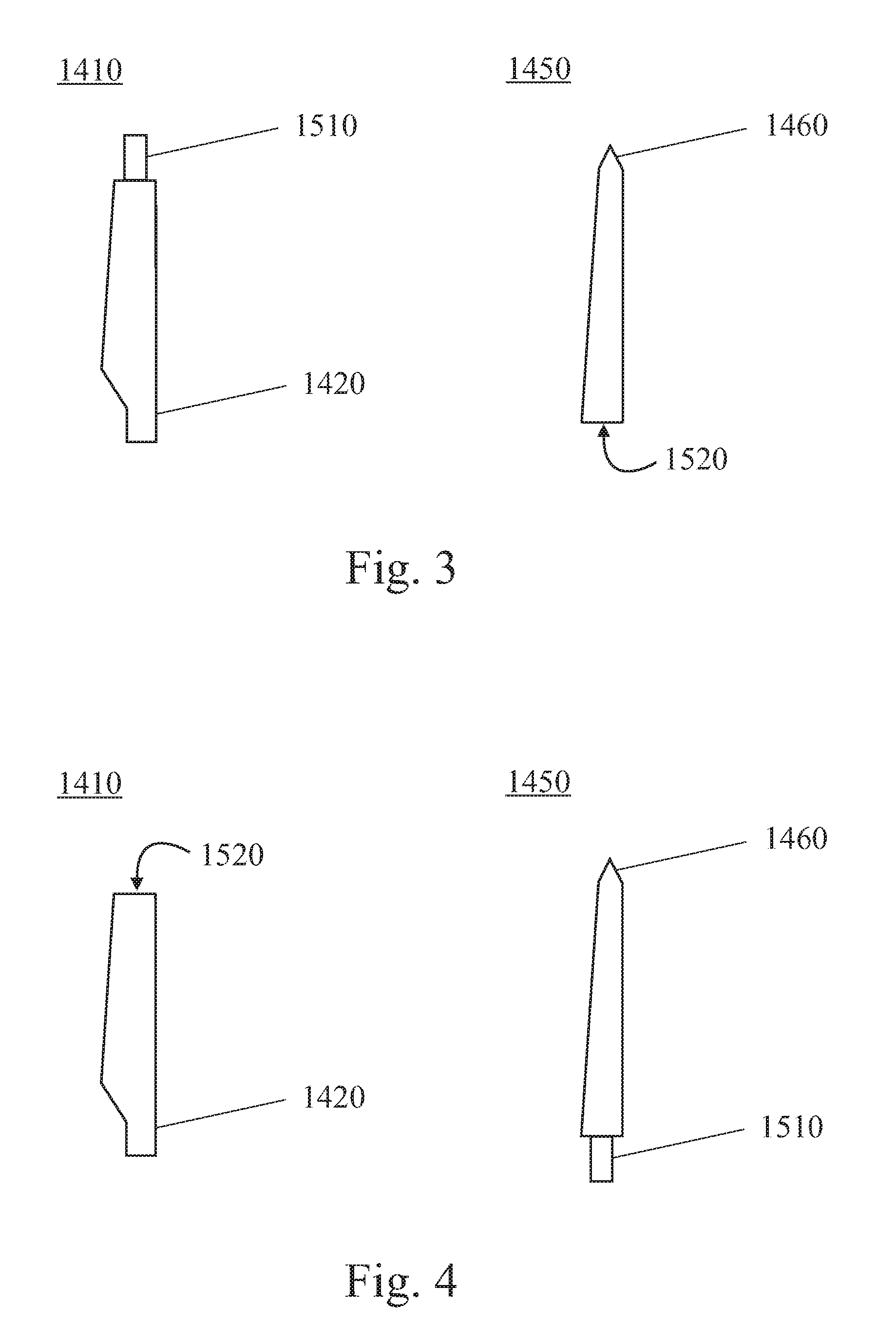
[0006] According to a first embodiment of the present invention, a sectional wind turbine rotor blade having first and second blade sections is provided. The first and second blade sections are fixedly mountable to each other by means of a connector. Due to the modular design of the rotor blade, the overall length of the sections to be transported is reduced compared to the longitudinal length of a non-modular rotor blade. Thus, transportation costs are considerably reduced. The provision of a connector has only a relatively low impact on blade structure and weight so that the operational properties of the rotor blade are not deteriorated.
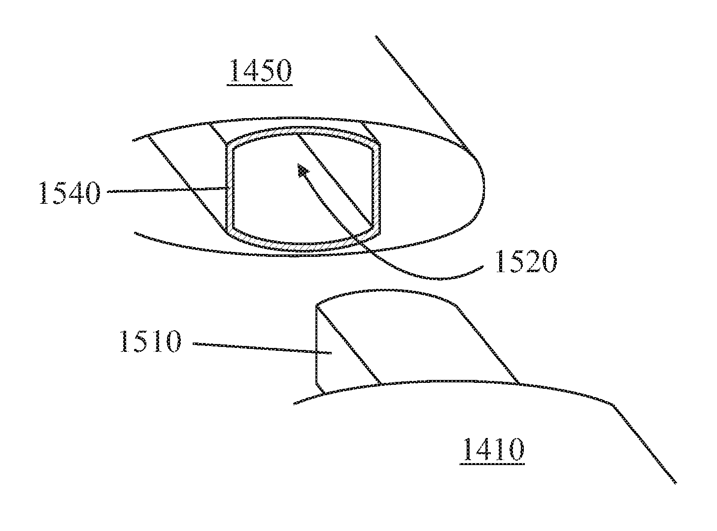
[0007] According to a further embodiment of the present invention, the connector includes a connector rod and a receptacle adapted to receive the rod. For example, the connector rod and the receptacle may be formed by male and female box beams which are adapted to fit into each other. The rod may be provided at a respective blade section or may be provided as a separate part. In the first case, a receptacle will be provided at the fitting module whereas, in the letter case, receptacles will be provided at the modules to be joined and the separate connector can be inserted in both receptacles. Such a plug and socket connection allows easy assembly of the blade modules at the construction site.
[0010] According to an even further embodiment of the present invention, the permanent connection between the modules is formed by vacuum infusion. This allows easy assembly and joining of the rotor blade modules.

Problems solved by technology

Since the number of profitable sites for wind energy production is limited, there is a tendency to increase the installed power per turbine.
Aside from the insufficient maneuverability of a vehicle transporting a 70 meter rotor blade, road transportation of rotor blades with 70 meters or more is extremely costly.
Furthermore, specific routes for the transport have to be followed since narrow curves cannot be passed.
Also loading and unloading of very long rotor blades from the truck is difficult.

Method used


Image

  • Modular rotor blade for a wind turbine and method for assembling same
  • Modular rotor blade for a wind turbine and method for assembling same
  • Modular rotor blade for a wind turbine and method for assembling same

Examples


Embodiment Construction

[0021] Reference will now be made in detail to the various embodiments of the invention, one or more examples of which are illustrated in the figures. Each example is provided by way of explanation of the invention, and is not meant as a limitation of the invention. For example, features illustrated or described as part of one embodiment can be used on or in conjunction with other embodiments to yield yet a further embodiment. It is intended that the present invention includes such modifications and variations.

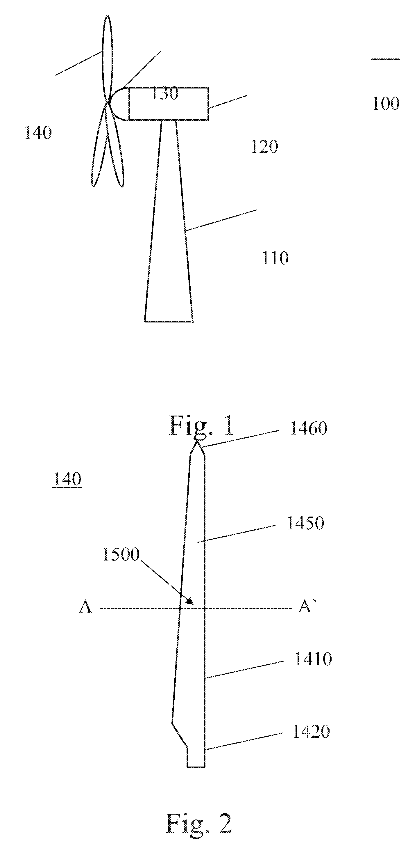
[0022]FIG. 1 shows a wind turbine 100 according to an embodiment of the present invention. The wind turbine 100 includes a tower 110, typically made of steel, to which a nacelle 120 is mounted. A rotor hub 130 is mounted to a lateral end of nacelle 120. Rotor blades 140 are mounted to rotor hub 130.

[0023]FIG. 2 shows a rotor blade 1400 according to an embodiment of the present invention. Rotor blade 1400 includes a first module 1410 and a second module 1450 which are joined ...


PUM

PropertyMeasurementUnit
Lengthaaaaaaaaaa
Bondaaaaaaaaaa

Abstract

A sectional wind turbine rotor blade is provided, the sectional wind turbine rotor blade having first and second blade sections, wherein the first and second blade sections are fixedly mountable to each other via a connector. Furthermore, a method for assembling a sectional wind turbine rotor blade is provided.

Description

FIELD OF THE INVENTION [0001] The present invention relates to a modular rotor blade for a wind turbine and a method for assembling such a modular rotor blade. BACKGROUND OF THE INVENTION [0002] In recent years, wind turbines have become more and more important in power generation. As a result, more and more wind turbines are installed. Since the number of profitable sites for wind energy production is limited, there is a tendency to increase the installed power per turbine. Since the installed power is proportional to the diameter of the turbine rotor, the rotor sizes and, accordingly, the turbine sizes increase. As a result, the length of the wind turbine rotor blades increases more and more. Typical blade lengths of current turbine designs are up to 70 meters or more. [0003] When assembling a wind turbine, the rotor blades have to be transported to the construction site by trucks on normal roads. Aside from the insufficient maneuverability of a vehicle transporting a 70 meter rot...

Claims


Application Information

Patent Timeline
IPC IPC(8): B64C27/46
CPCF03D1/0675F03D11/00F05B2230/60Y10T29/49337Y02E10/721Y02E10/722F05B2250/70F05B2240/302Y02E10/72Y02P70/50
Inventor EYB, ENNO
Owner GENERAL ELECTRIC CO
Learn More