Eureka AIR delivers breakthrough ideas for toughest innovation challenges, trusted by R&D personnel around the world.

Guidewire Separator Device and Method of Use

a separator device and guidewire technology, applied in the field of guidewires, catheters and catheter systems, can solve the problems of difficult separation, guidewire twisting around one another, entanglement, etc., and achieve the effect of quick and easy separation

Inactive Publication Date: 2007-10-25
MINVASYS SA
View PDF49 Cites 49 Cited by
  • Summary
  • Abstract
  • Description
  • Claims
  • Application Information

AI Technical Summary

Benefits of technology

[0054] In keeping with the foregoing discussion, it would be desirable therefore to provide a device and methods that can be used electively to either prevent guidewire entanglement or, if the need arises, to quickly and easily separate the entangled guidewires and / or to assist in proper placement of the guidewires into their respective branches of the bifurcation. Preferably, the device and methods would not require the use of exchange length guidewires or guidewire extensions. Such a device and methods would not disrupt the normal routine in the majority of cases where the problem of guidewire entanglement does not occur, but could be readily available for use in resolving problems when they arise.
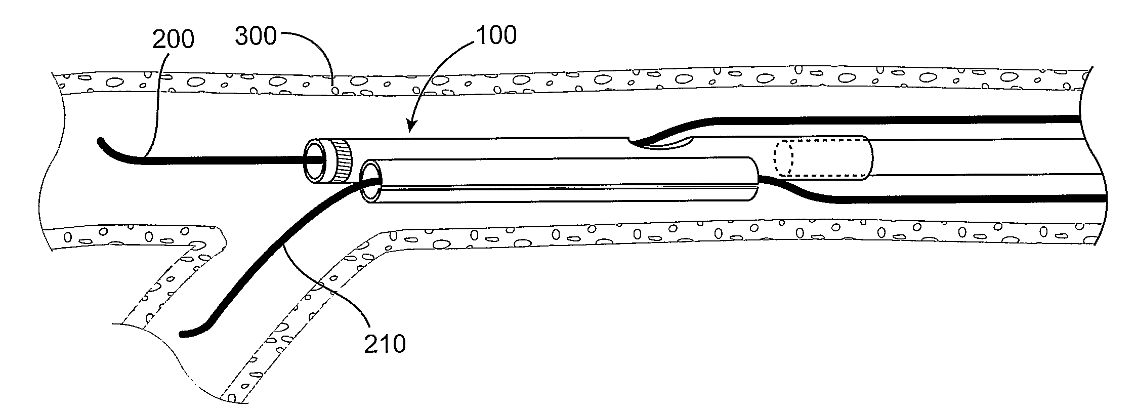
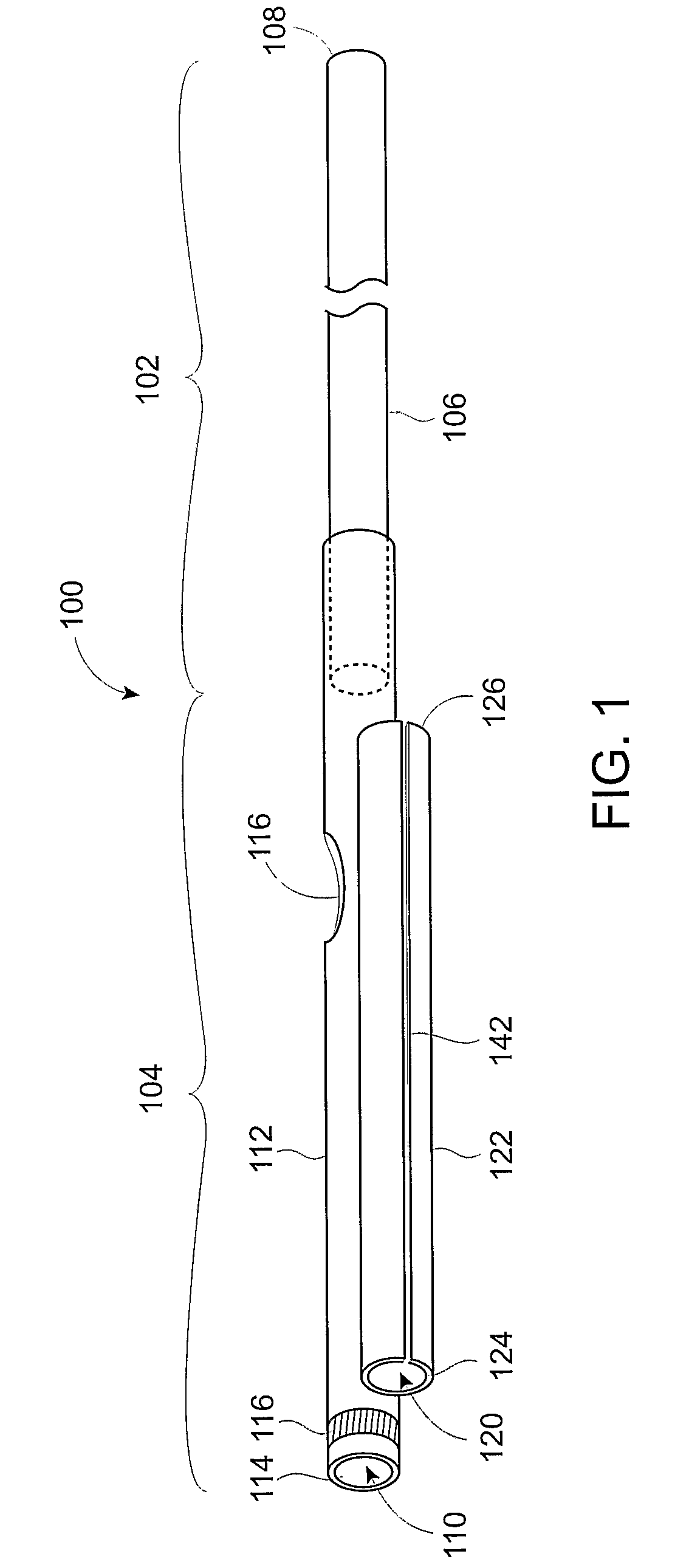
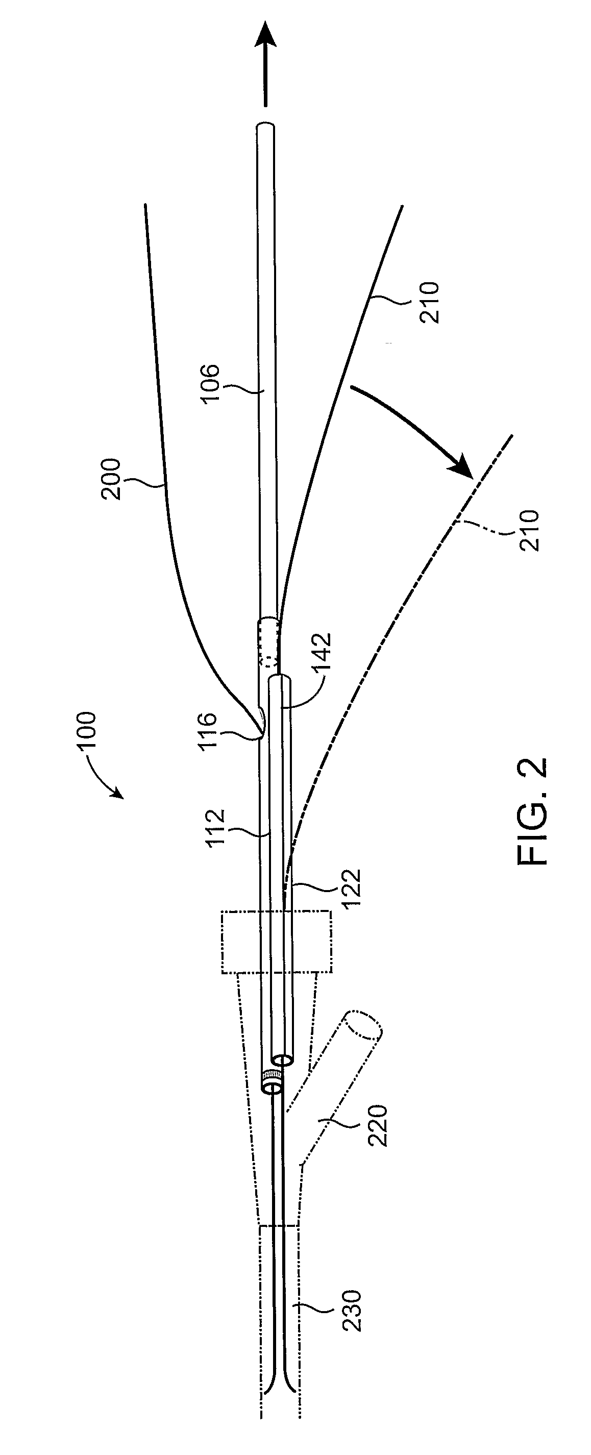
[0055] A guidewire separator device and methods of use are described for preventing guidewire entanglement and for quickly and easily separating entangled guidewires and assisting in proper placement of the guidewires into their respective branch vessels when performing angioplasty or stenting of a bifurcated artery. The guidewire separator device has an elongate tubular distal portion joined to an elongate proximal portion. A first lumen extends through at least the tubular distal portion of the device, with a first distal guidewire port located near a distal end of the distal portion and a first proximal guidewire port located near a proximal end of the distal portion. A second lumen extends through at least the tubular distal portion of the guidewire separator device, with a second distal guidewire port located near a distal end of the distal portion and a second proximal guidewire port located near a proximal end of the second lumen. Optionally, the guidewire separator device includes a longitudinal slit in a sidewall of the device that communicates with the second lumen.

Problems solved by technology

Difficulties can arise when attempting to position the first and second guidewires in the branches of the bifurcated vessel.
Because of the manipulations that may be necessary to maneuver the guidewires into each of the branches, there is a possibility that the guidewires may twist around one another and become entangled.
This problem is more common when one or both of the branches is difficult to engage with the guidewire, requiring additional manipulations to maneuver the guidewires into their respective branches of the bifurcation.
This method must be used preemptively to avoid guidewire entanglement and cannot readily be used to separate the guidewires after they have become entangled.
Routine use of this method would add an unnecessary device and unnecessary method steps to many procedures where it may not have been needed.
In addition, the configuration in some embodiments of the guidewire introducer sheath requires that exchange length guidewires or guidewire extensions be used for the procedure, which also adds more expense and complexity to the procedure.

Method used


Image

  • Guidewire Separator Device and Method of Use
  • Guidewire Separator Device and Method of Use
  • Guidewire Separator Device and Method of Use

Examples


Embodiment Construction

[0071]FIG. 1 shows a guidewire separator device 100 according to the present invention. The guidewire separator device 100 is constructed with a distal portion 104 having a first lumen 110 and a second lumen 120. The distal portion 104 is mounted to or otherwise connected to a proximal portion 102. The distal portion 104 may be formed of two tubes 112, 122 joined together side-by-side or it may be formed from a two-lumen tube. In a preferred embodiment, the distal portion 104 is constructed of a flexible polymer extrusion, preferably with a polymer having a relatively low coefficient of friction. Suitable materials include, but are not limited to polyethylene, polypropylene, polyolefins, polyamides, polyamide copolymers, PTFE, FEP, and any extrudable medical grade polymer with a suitable combination of strength, flexibility and friction characteristics. The proximal portion 102 may be configured as a straight wire or stylet 106 joined to the distal portion 104, which may be formed f...


PUM


Abstract

A guidewire separator device and methods are described for resolving guidewire entanglement and for introducing guidewires into branch vessels when performing angioplasty or stenting of a bifurcated artery. The device has an elongate tubular distal portion joined to an elongate proximal portion. A first lumen extends through the tubular distal portion of the device, with a first distal guidewire port located near a distal end of the distal portion and a first proximal guidewire port located near a proximal end of the distal portion. A second lumen extends through the tubular distal portion of the device, with a second distal guidewire port located near a distal end of the distal portion and a second proximal guidewire port located near a proximal end of the second lumen. One or both of the lumens may continue through the proximal portion of the device. Optionally, the device includes one or more longitudinal slits to externalize the guidewires from the lumens during withdrawal of device.

Description

FIELD OF THE INVENTION [0001] The present invention relates generally to guidewires, catheters and catheter systems, such as those used for performing angioplasty and vascular stenting. More particularly it relates to a guidewire separator device and method of use for catheterizing or stenting a vessel at a bifurcation or sidebranch of the vessel. BACKGROUND OF THE INVENTION [0002] One of the techniques commonly used for performing angioplasty and vascular stenting of a vessel at a bifurcation or sidebranch of the vessel is known as the “kissing balloons” technique. Improvements to the “kissing balloons” technique are disclosed in commonly owned and copending U.S. patent application for Catheter System for Stenting Bifurcated Vessels, Ser. No. 10 / 833494, filed on Apr. 27, 2004. This application and all patents and patent applications referred to herein are incorporated by reference in their entirety. [0003] One common method of performing the “kissing balloons” technique involves in...

Claims


Application Information

Patent Timeline
IPC IPC(8): A61M31/00A61B17/22A61B17/32A61F2/06A61F2/84A61M25/00
CPCA61B2017/22038A61F2/856A61F2/954A61M25/0029A61M25/0068A61M25/0071A61M2025/1045A61M2025/0034A61M2025/0037A61M2025/004A61M2025/0063A61M2025/018A61M2025/0188A61M25/008
Inventor HILAIRE, PIERREVAN DER LEEST, MACHIELROYER, THIERRY
Owner MINVASYS SA
Why Eureka
Eureka Blog
Learn More