Roller bearing cage, roller bearing, and method of producing roller bearing race and roller bearing outer ring
a roller bearing and cage technology, applied in the field of roller bearings, can solve the problems of decreasing the number of rollers being able to be arranged, the inability to secure the bonding strength, and the inability to arrange the rollers, and achieve the effect of sufficient strength
- Summary
- Abstract
- Description
- Claims
- Application Information
AI Technical Summary
Benefits of technology
Problems solved by technology
Method used
Image
Examples
first embodiment
Thrust Roller Bearing Cage
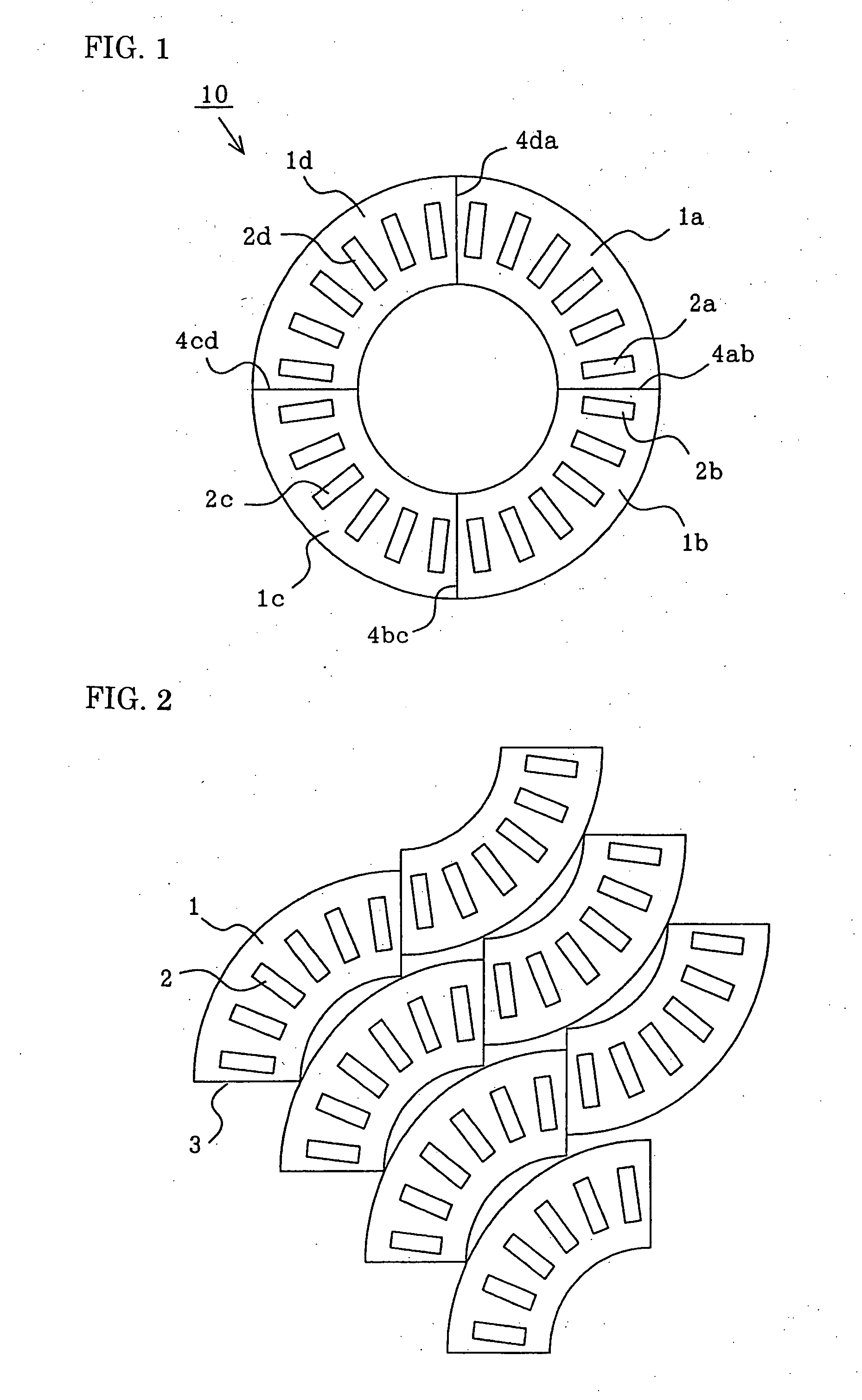
[0046]FIG. 1 is a plan view showing a thrust roller bearing cage according to a first embodiment of the invention. Referring to FIG. 1, a thrust roller bearing cage (hereinafter referred to as “thrust cage”) 10 is a plate-shape circular ring which is formed by laser-welding four arcuate pieces 1a, 1b, 1c, and 1d. In each of the arcuate pieces 1a, 1b, 1c, and 1d, rectangular pockets 2a, 2b, 2c, 2d are formed at regular intervals, respectively.
[0047] The arcuate pieces 1a and 1b are laser-welded at a laser welding line 4ab, the arcuate pieces 1b and 1c are laser-welded at a laser welding line 4bc, the arcuate pieces 1c and 1d are laser-welded at a laser welding line 4cd, and the arcuate pieces 1d and 1a are laser-welded at a laser welding line 4da. In the following description, subscripts of “a, b, c, d, ab, bc, cd, and da” are neglected for the common contents.
[0048] Because the laser welding line 4 has a narrow width, a distance between a pair of pockets...
second embodiment
Thrust Roller Bearing
[0055] A thrust roller bearing according to a second embodiment of the invention (not shown) includes a pair of rolling bearing rings formed by plate-shape circular rings, plural freely-rolling rollers arranged between the rolling bearing rings, and the thrust cage 10 (see FIG. 1) in which the rollers are arranged in a radial direction.
[0056] Therefore, because the thrust cage 10 has the above-described effect, in the thrust roller bearing of the second embodiment, the production cost is reduced, the predetermined number of rollers can be arranged (namely, predetermined thrust power can be supported), the operating life is lengthened, and the reliability is improved.
third embodiment
Radial Roller Bearing Cage
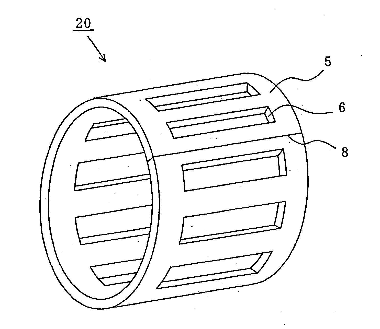
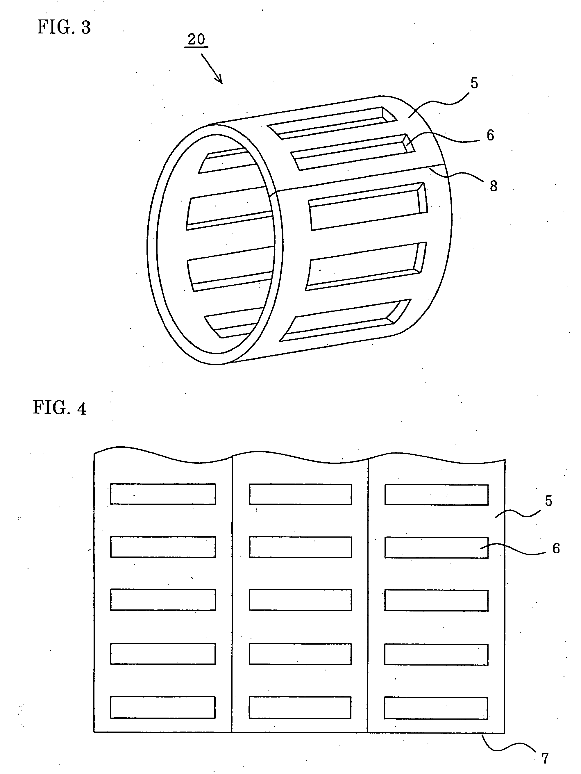
[0057]FIG. 3 is a perspective view showing a radial roller bearing cage according to a third embodiment of the invention. Referring to FIG. 3, in a radial roller bearing cage (hereinafter referred to as “radial cage”) 20, one strip-shape element 5 is formed in a cylindrical shape, and end portions 7 are laser-welded at a laser welding line 8. Plural rectangular pockets 6 are formed all around at regular intervals.
[0058] Because the laser welding line 8 has the narrow width, the distance between the pair of pockets 6 arranged across the laser welding line 8 can be equalized to the distance between a pair of pockets 6 which are adjacent to each other while not arranged across the laser welding line 8. Namely, the pockets 6 can be arranged all around at regular intervals irrespective of existence of the laser welding line 8. Therefore, the rollers can be arranged as many as rollers in a radial cage formed by the deep drawing (having no welded structure).
[00...
PUM
| Property | Measurement | Unit |
|---|---|---|
| Length | aaaaa | aaaaa |
| Thickness | aaaaa | aaaaa |
| Strength | aaaaa | aaaaa |
Abstract
Description
Claims
Application Information
 - R&D
- Intellectual Property
- Life Sciences
- Materials
- Tech Scout
- Unparalleled Data Quality
- Higher Quality Content
- 60% Fewer Hallucinations
Browse by: Latest US Patents, China's latest patents, Technical Efficacy Thesaurus, Application Domain, Technology Topic, Popular Technical Reports.
© 2025 PatSnap. All rights reserved.Legal|Privacy policy|Modern Slavery Act Transparency Statement|Sitemap|About US| Contact US: help@patsnap.com


