
System for 2-D and 3-D Vision Inspection

a technology of vision inspection and system, applied in the field of inspection systems, can solve the problems of slow inspection throughput, complicated system, and high cost of setup

Active Publication Date: 2007-10-25
MIT SEMICON (TIAN JIN) CO LTD
View PDF2 Cites 24 Cited by
  • Summary
  • Abstract
  • Description
  • Claims
  • Application Information

AI Technical Summary

Benefits of technology

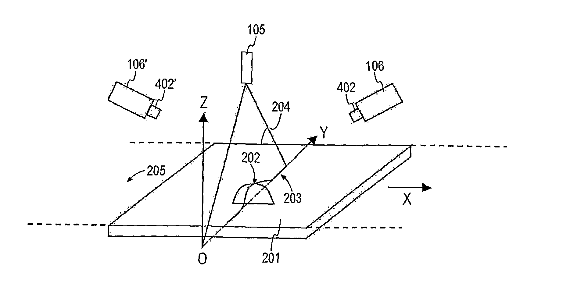
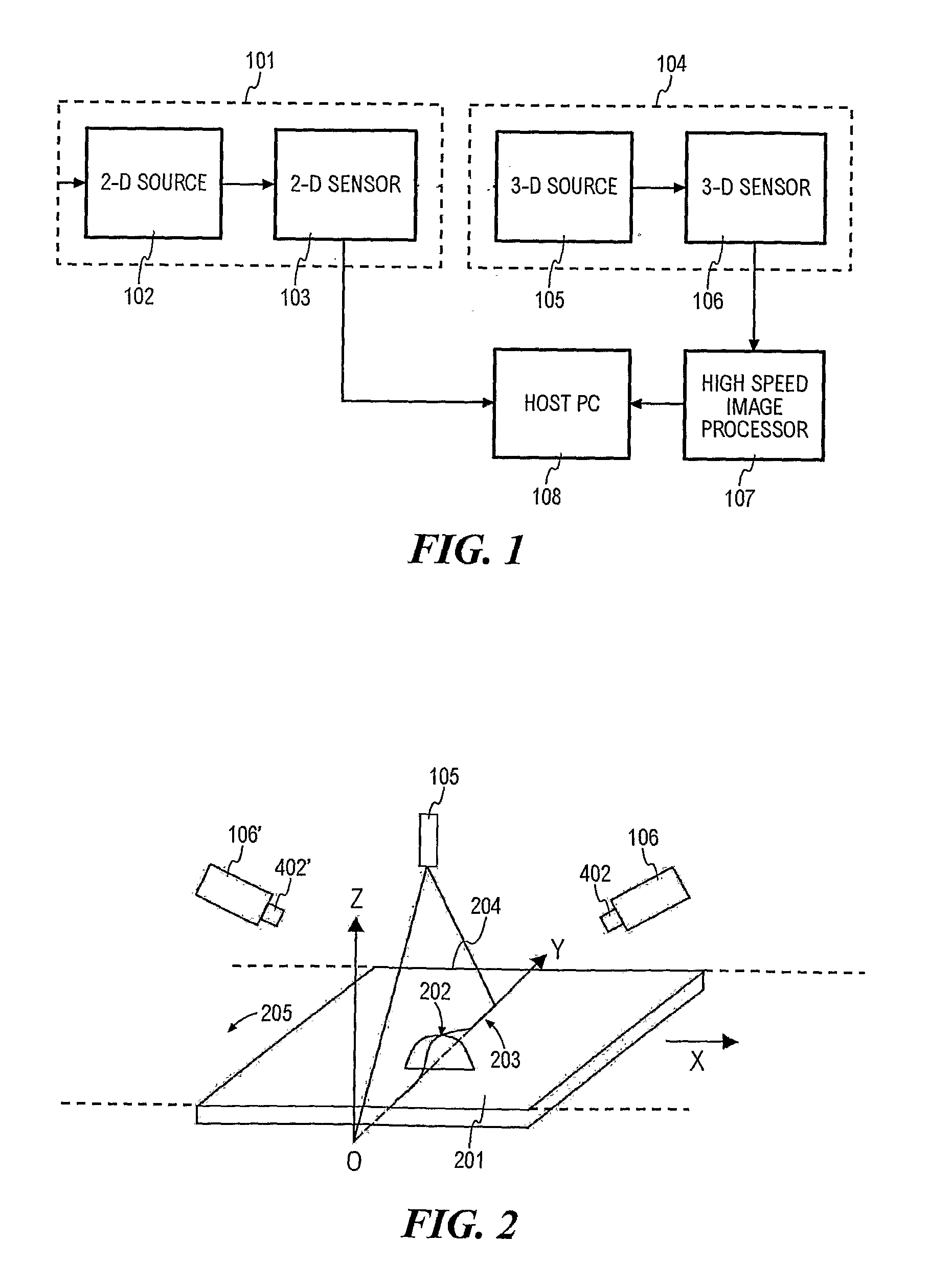
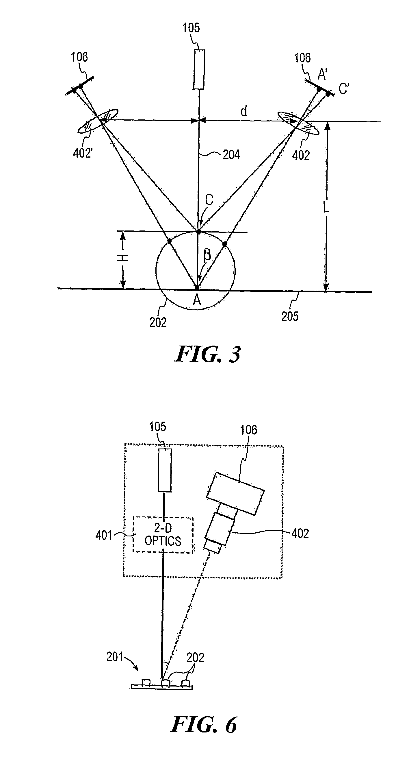
[0007] The present invention is directed to an inspection system that combines 2-D inspection and 3-D inspection of the components of an electronic device into one compact module. The inspection system of the present invention comprises, a 2-D image acquisition assembly for inspecting 2-D criteria of the components, a 3-D image acquisition assembly for inspecting 3-D criteria of the components, and a processing unit connected to the 2-D image acquisition assembly and the 3-D image acquisition assembly for analyzing the 2-D and the 3-D images. The 3-D image acquisition assembly comprises a 3-D image sensor and a 3-D light source. The 3-D light source is preferably a laser capable of generating a planar sheet of light that is substantially perpendicular to the plane of the electronic device. The 2-D image acquisition assembly comprises a 2-D sensor and a 2-D light source positioned above the holder. The 2-D and 3-D image acquisition assemblies are arranged so that the 2-D inspection and 3-D inspection can be done while the electronic device is being held in one location.
[0008] The present invention combines 2-D and 3-D inspection function into one module with a beam splitter. 2-D and 3-D systems are aligned so that they have the same center in field of view. Different cameras are utilized because of different requirements and selection criteria. The 2-D camera is a normal camera, typically is a CCD camera. It concentrates on 2-D feature inspection such as the location and dimension of ball / lead and defects on the device surface etc. The 3-D camera is a high speed CMOS sensor camera with programmable window size working together with a high-speed data process hardware unit.

Problems solved by technology

The disadvantages of ‘134’ are that it has different centers in field of view for 2-D and 3-D respectively, and requires a separate mechanism to pick up and orientate the targeted device before inspection can be performed.
One disadvantage of this system is that one camera are used for both 2D and 3D inspection, which will slow down the inspection throughput.
The disparity in the amount of data input from 2-D and 3-D criteria becomes a bottleneck for the inspection speed of the inspection system that uses only one camera.
This system is complicated and expensive to set up.

Method used


Image

  • System for 2-D and 3-D Vision Inspection
  • System for 2-D and 3-D Vision Inspection
  • System for 2-D and 3-D Vision Inspection

Examples


Embodiment Construction

[0019]FIG. 1 shows a schematic block diagram representing the basic arrangement of the inspection system according to the preferred embodiment of the present invention. The inspection system of the present invention comprises four basic components: a 2-D image acquisition assembly 101, which includes a 2-D light source 102 and a 2-D sensor 103; a 3-D image acquisition assembly 104, which includes a 3-D light source 105 and one or two 3-D sensor 106; a host programmable computer (PC) 108; and a high speed image processor 107. The 2-D light source 101 illuminates an electronic device to be inspected, e.g. an IC package. The 2-D image of the components of the electronic device is then captured by the 2-D sensor 102. The 2-D image is sent to host 108 for performing 2 dimensional images processing tasks. At the same time, the 3D light source 105 is activated to illuminate the device while it is being held in the same location. The 3-D image of the components is captured by the 3-D sensor...


PUM

PropertyMeasurementUnit
acute angleaaaaaaaaaa
field of viewaaaaaaaaaa

Abstract

There is disclosed an inspection system that combines 2-D inspection and 3-D inspection of the components of an electronic device into one compact module. The inspection system of the present invention comprises a 2-D image acquisition assembly for inspecting 2-D criteria of the components, a 3-D image acquisition assembly for inspecting 3-D criteria of the components, and a computer for control and data analyzing. The 3-D image acquisition assembly comprises a 3-D image sensor and a 3-D light source. The 3-D light source is preferably a laser capable of generating a planar sheet of light that is substantially perpendicular to the inspection plane of the electronic device. The 2-D image acquisition assembly comprises a 2-D sensor and a 2-D light source positioned above the holder. The 2D and 3D image acquisition assemblies are arranged so that the 2D inspection and 3D inspection can be done while the electronic device is being held in one location.

Description

FIELD OF THE INVENTION [0001] The present invention relates generally to an inspection system that performs three dimensional (3-D) and two dimensional (2-D) criteria analysis. More specifically, the 3-D and 2-D criteria analysis is used to perform inspection of integrated circuit (IC) devices. BACKGROUND OF THE INVENTION [0002] There is a need in the manufacturing of IC devices for inspection of electronic components such as leads and solder balls of semiconductor packages. Several systems are available for separate 2-D and 3-D inspection of semiconductor packages. [0003] U.S. Pat. No. 5,956,134 discloses a lead inspection system that is operable to make both 2-D and 3-D measurements of semiconductor packages while there are relative movement between the lead inspection system and the semiconductor packages. This system includes a first optical sensor, e.g. a CCD camera, oriented to capture a 2-D image of a semiconductor device package and compare the image with a predetermined 2-D...

Claims


Application Information

Patent Timeline
Patent Type & Authority Applications(United States)
IPC IPC(8): G01N21/00
CPCH05K13/08G01N21/95684H05K13/0813
Inventor PUAH, YONGTANG, HAKHUA, FAN
Owner MIT SEMICON (TIAN JIN) CO LTD
Learn More