
Method for calibrating a radiation detection medium

a radiation detection medium and calibration method technology, applied in the direction of x/gamma/cosmic radiation measurement, radioation particle tracking, instruments, etc., can solve the problem of only reproducing the pattern of predefined areas, unable to maintain the registration of films to the radiotherapy treatment system, and unable to reproduce predefined areas. problems, to achieve the effect of avoiding potential overlap

Active Publication Date: 2007-10-25
ISP INVESTMENTS LLC
View PDF1 Cites 10 Cited by
  • Summary
  • Abstract
  • Description
  • Claims
  • Application Information

AI Technical Summary

Benefits of technology

[0011] In accordance with certain aspects of the present invention, the scanned image is analyzed through the use of a software program that extracts possible candidates of the irradiated detection medium that satisfy certain criteria. The specified criteria are selected to identify those areas that are representative of an irradiated area on the detecti

Problems solved by technology

However, there are certain drawbacks to a calibration based on exposing predefined regions of the radiation detection medium.
As the radiation detection medium is placed in position by a combination of manual and visual means, it can be difficult to maintain precise registration of the film to the radiotherapy treatment system.
Another source of possible error in the use of predefined areas for generating a calibration curve is related to reading and measuring of the radiation detection medium using a film scanner.
Accordingly, any mis-registration of the radiation detection medium with respect to either the radiotherapy treatment system or the film scanning system will typically lead to an error in measurement of the exposed areas in a system that automatically takes measurements in the predefined areas.
Yet another source of possible error in the use of pre-defined areas of exposure can result from mis-orientation of a radiation detection medium on a scanner.
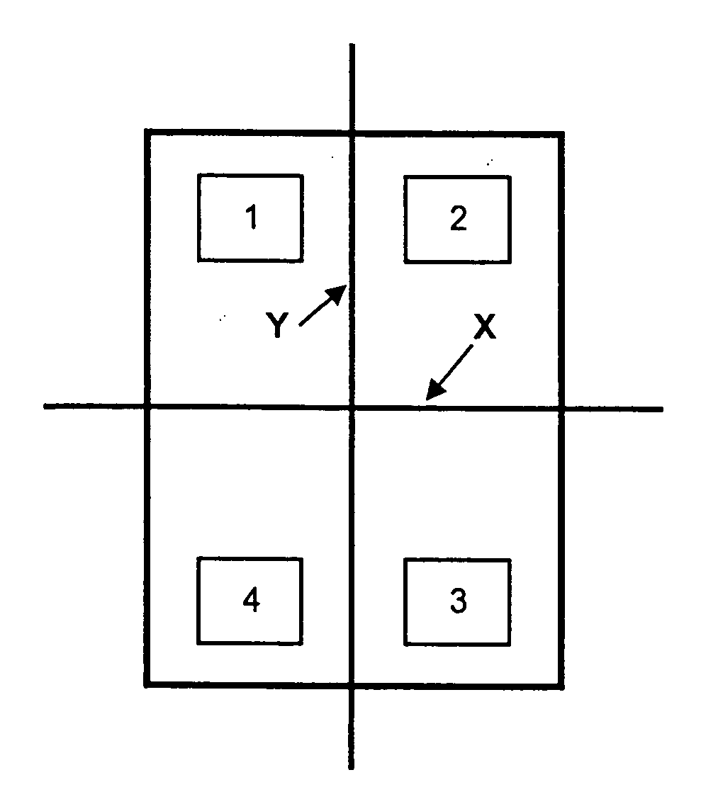
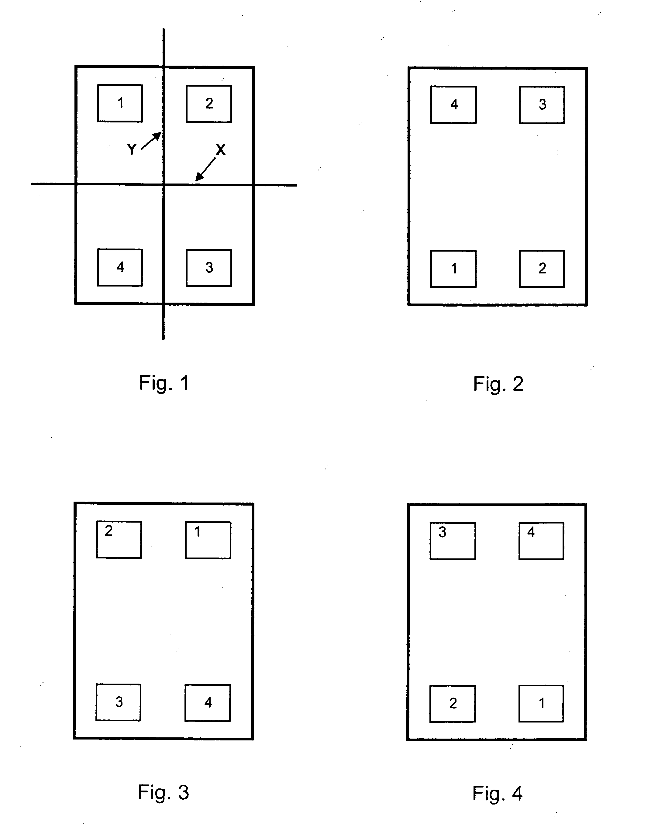
In particular, if the pre-defined areas do not form a symmetric pattern on the detection medium then the pattern of predefined areas can only be reproduced if the film is placed on the scanner in the correct orientation.

Method used


Image

  • Method for calibrating a radiation detection medium
  • Method for calibrating a radiation detection medium

Examples


Embodiment Construction

[0016] The following detailed description is intended to be representative only and not limiting as to the described method for calibrating a radiation detection medium. Many variations can be devised by one skilled in this area of technology, which are included within the scope of the present invention. The following detailed discussion of the various alternative and preferred embodiments will illustrate the general principles of the invention.

[0017] For the discussion below, the following terms are defined as follows:

[0018] The term “radiation detection medium” as used herein generally refers to a medium that undergoes a detectable change when exposed to radiation. The change may be immediately visible as with radiochromic film. Alternatively the change may produce a latent image, such as in silver-based films, that requires a chemical or physical development process before it is visible. Still other radiation detection media such as diode arrays, ion chamber arrays, CR plates o...


PUM


Abstract

A method for calibrating a radiation detection medium by exposing arbitrary locations of a radiation detection medium to a plurality of known radiation dose levels is described. One particular aspect of the method includes the steps of automatically determining the location of each arbitrary exposed location, measuring the density of each of the arbitrary exposed locations, matching each measurement for the arbitrary exposed locations with the corresponding radiation dose level thereby generating an array of paired data values for radiation dose level and measured density and calculating a calibration based on the array of paired data values.

Description

BACKGROUND [0001] The present invention relates to calibration of a radiation detection medium in a radiotherapy treatment system, and in particular, to methods for calibrating a radiation detection medium in a radiotherapy treatment system wherein the calibration is determined by exposing arbitrary areas of the medium to a plurality of dose levels. [0002] Radiotherapy has been used for years as a method for irradiating and selectively killing cancer cells while minimizing radiation exposure to adjacent tissue. The effectiveness of radiotherapy can depend upon the absorbed dose or the amount of energy deposited within a tissue mass. Absorbed dose is typically measured in centigray or cGy units. [0003] A radiation detection medium may be used to determine the amount of radiation to which a patient is subjected during radiation treatment. Particularly useful is a two-dimensional or three-dimensional radiation detection medium that can determine radiation dose over an area or within a ...

Claims


Application Information

Patent Timeline
IPC IPC(8): G01T1/02
CPCG01T7/005G01T1/02
Inventor LEWIS, DAVID F.
Owner ISP INVESTMENTS LLC
Learn More