
Sensor Element for Determining a Physical Property of a Measuring Gas

a technology of a sensor element and a physical property, which is applied in the direction of measuring devices, instruments, material electrochemical variables, etc., can solve the problems of stress cracks in the solid electrolyte body, reduced functionality, and accelerated aging of the reference electrod

Inactive Publication Date: 2007-10-25
ROBERT BOSCH GMBH
View PDF9 Cites 13 Cited by
  • Summary
  • Abstract
  • Description
  • Claims
  • Application Information

AI Technical Summary

Benefits of technology

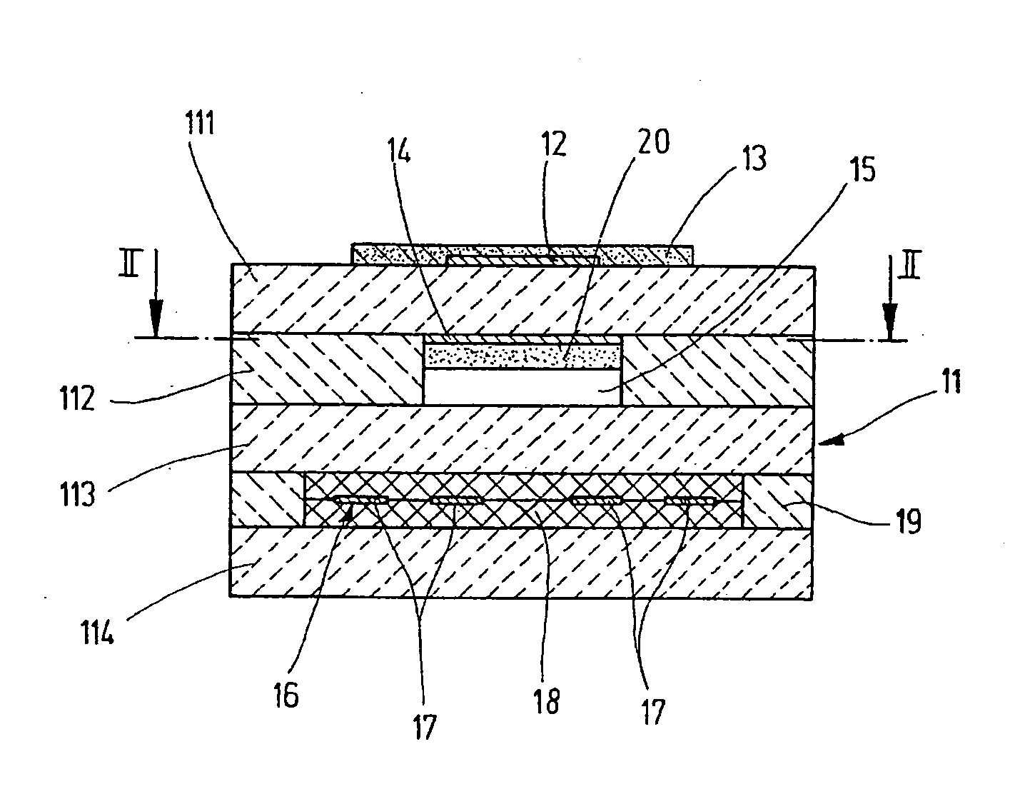
[0005] The sensor element according to the present invention has the advantage that through the selection of the volume material, through which the reference gas is applied to the reference electrode, with respect to its physical and chemical properties, in particular with respect to its affinity for binding the foreign substances normally present in the reference gas, the foreign substances are bound in the porous volume or enter into a chemical reaction in the porous volume and are thus unable to interact with the electrode surface of the reference electrode. Since the reference electrode is generally situated in a reference channel formed in the interior of the solid electrolyte, the requirements placed on the mechanical strength of the volume material are not high.

Problems solved by technology

In addition, the porous layer reduces increased mechanical stresses which occur on the edge of the reference gas channel toward the adjacent solid electrolyte and which may result in stress cracks in the solid electrolyte body.
In sensor elements of this type, functionality is reduced over the long term due to aging processes.
However, the reference gas, in particular when the ambient air in the engine compartment of a motor vehicle is used as a reference gas, also contains contaminants—even if only a small amount—which result in accelerated aging of the reference electrode.

Method used


Image

  • Sensor Element for Determining a Physical Property of a Measuring Gas
  • Sensor Element for Determining a Physical Property of a Measuring Gas
  • Sensor Element for Determining a Physical Property of a Measuring Gas

Examples


Embodiment Construction

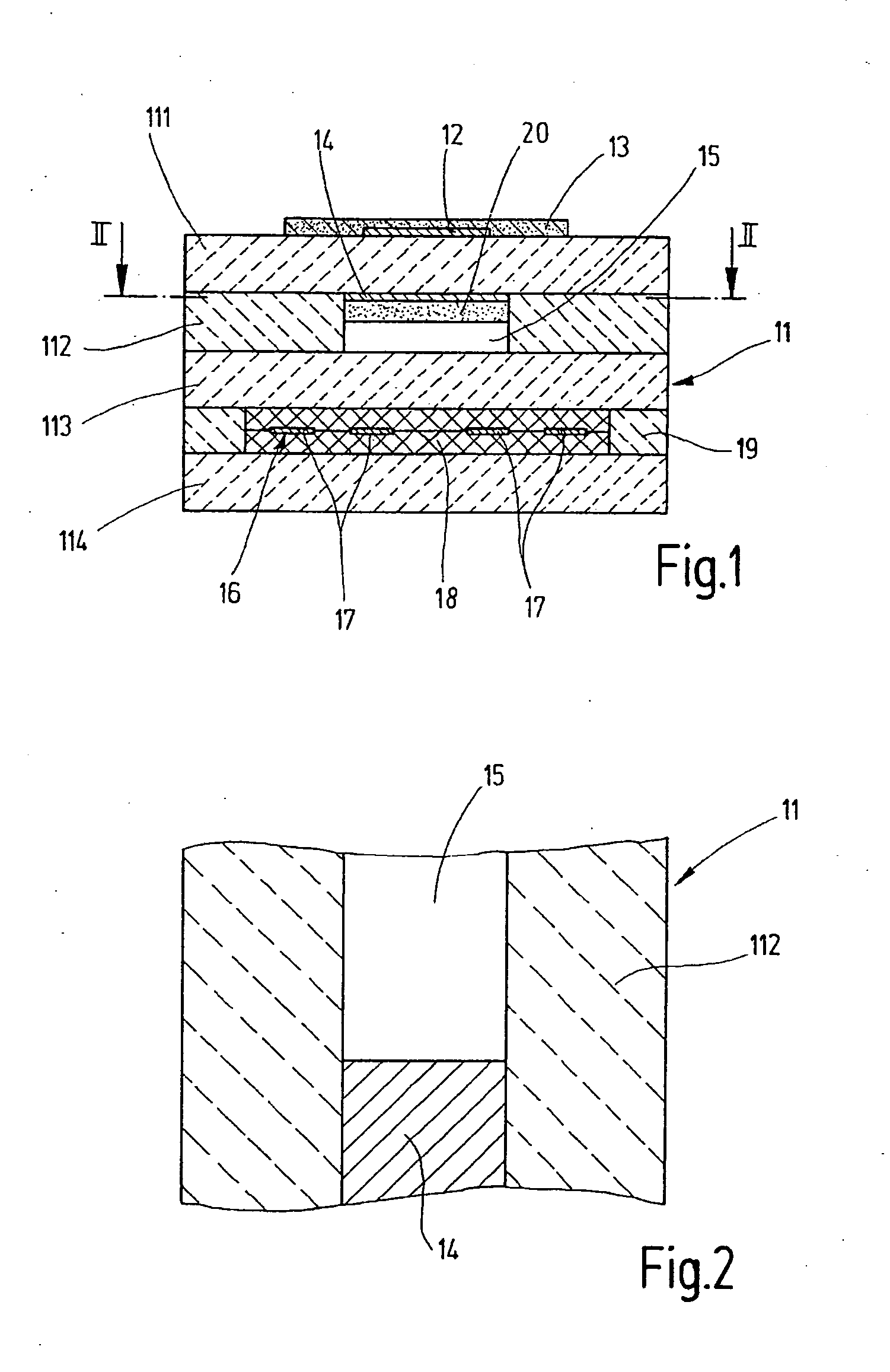
[0012] The sensor element shown in two different sectional views in FIGS. 1 and 2 for a lambda sensor, operating according to the Nernst (potentiometric) principle for measuring the oxygen concentration in the exhaust gas of an internal combustion engine, as an exemplary embodiment of a general sensor element for determining a physical property of a measuring gas, has a solid electrolyte body 11, which is made up of a plurality of oxygen-conducting solid electrolyte layers 111 through 114, which are in part designed as ceramic films such as solid electrolyte layers 111, 112, and 114 and in part as a printed layer such as solid electrolyte layer 113. Zirconium oxide (ZrO2) fully or partially stabilized by yttrium, for example, is used as a solid electrolyte material. The integrated form of planar ceramic solid electrolyte body 11 is produced by laminating together the ceramic films printed with functional layers and subsequently sintering the laminated structure.

[0013] On first soli...


PUM

PropertyMeasurementUnit
thicknessaaaaaaaaaa
porosityaaaaaaaaaa
thicknessaaaaaaaaaa

Abstract

A sensor element is described for determining a physical property of a measuring gas, in particular the pressure or the concentration of a gas component in a gas mixture, in particular in the exhaust gas of an internal combustion engine. The sensor element has an electrode exposed to the measuring gas and a reference electrode exposed to a reference gas, ambient air in particular, through a porous volume. The two electrodes are separated from one another by a solid electrolyte. To avoid premature aging of the reference electrode as a result of deposits of foreign substances contained in the reference gas or of chemical interactions caused by the foreign substances, the volume material is selected with respect to its physical and chemical properties in such a way that the foreign substances are bound in the volume and / or are subjected to a chemical reaction.

Description

FIELD OF THE INVENTION [0001] The present invention is directed to a sensor element for determining a physical property of a measuring gas, in particular the pressure or the concentration of a gas component in a gas mixture, in particular in the exhaust gas from an internal combustion engine. BACKGROUND INFORMATION [0002] In a known electrochemical sensor for determining the oxygen content in gas mixtures having a heating device for generating the operating temperature of the sensor element (German Published Patent Application No. 198 15 700), the volume provided with pores via which the reference electrode is connected to a reference gas channel conveying the reference gas is formed as a layer plane between the reference channel and the reference electrode and is used for improved thermal coupling between the reference electrode and the resistance heating element of the heating device, providing uniform heat distribution. In addition, the porous layer reduces increased mechanical s...

Claims


Application Information

Patent Timeline
Patent Type & Authority Applications(United States)
IPC IPC(8): G01N27/26G01N27/407
CPCG01N27/4071
Inventor SCHNEIDER, JENSHEIMANN, DETLEFWAHL, THOMASEGNER, THOMASSCHNEIDER, GERHARDRENZ, HANS-JOERGNEUMANN, HARALDSCHAAK, ANDREAS
Owner ROBERT BOSCH GMBH
Learn More