
Profiled Frame as a Component of a Window or Door

Inactive Publication Date: 2007-10-25
EMKA BESCHLAGTAILE GMBH & CO KG
View PDF15 Cites 6 Cited by
  • Summary
  • Abstract
  • Description
  • Claims
  • Application Information

AI Technical Summary

Benefits of technology

[0009]The inventive profiled frame has the advantage that a machining of the profiled frame member for the mounting of hinges or hinge parts is entirely avoided since the hinge shaft is supported by the molded elements, which are positively held in the profiled frame member, and the hinges, which are monolithically formed, are adapted to be shoved or inserted onto the hinge shaft by means of the hinge bore. Thus, not only are the hinges themselves configured in a more straightforward manner as monolithic components, and therefore can be produced more economically, but rather also mounting of the hinges on the profiled frame is simplified, since the individual components, such as the molded elements, the hinge shaft and the hinges, merely need to be inserted into one another. In this connection, the arrangement or position of the hinges can advantageously be variably determined, because the molded elements that are disposed between the hinges function as spacers for the hinges and can thus be cut to an appropriate length from an initially continuous profiled element in conformity with the desired arrangement of the hinges on the profiled frame.
[0010]Pursuant to one embodiment of the invention, the monolithic hinge comprises a hinge leaf having the hinge bore at one of its ends and a mounting leg on the other end of the hinge leaf for mounting of the hinge on a component that carries the door or the window. Such hinges are easy to produce.

Problems solved by technology

Known windows or doors of circumferential profiled frames having variously configured profiled frame members have the drawback that for the mounting of hinges or hinge components on the profiled frame, the profiled frame member must at a later point in time be notched or recessed at the pertaining location that is provided for the hinge of the window or door in order to be able to secure to the profiled frame one part of a generally two-part hinge, whereby the hinge part that is thus secured to the window or the door is installed together with an associated counter member of the hinge via a hinge shaft, or must be mounted together upon final installation of the window or door.

Method used


Image

  • Profiled Frame as a Component of a Window or Door
  • Profiled Frame as a Component of a Window or Door

Examples


Embodiment Construction

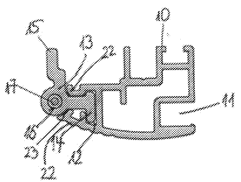
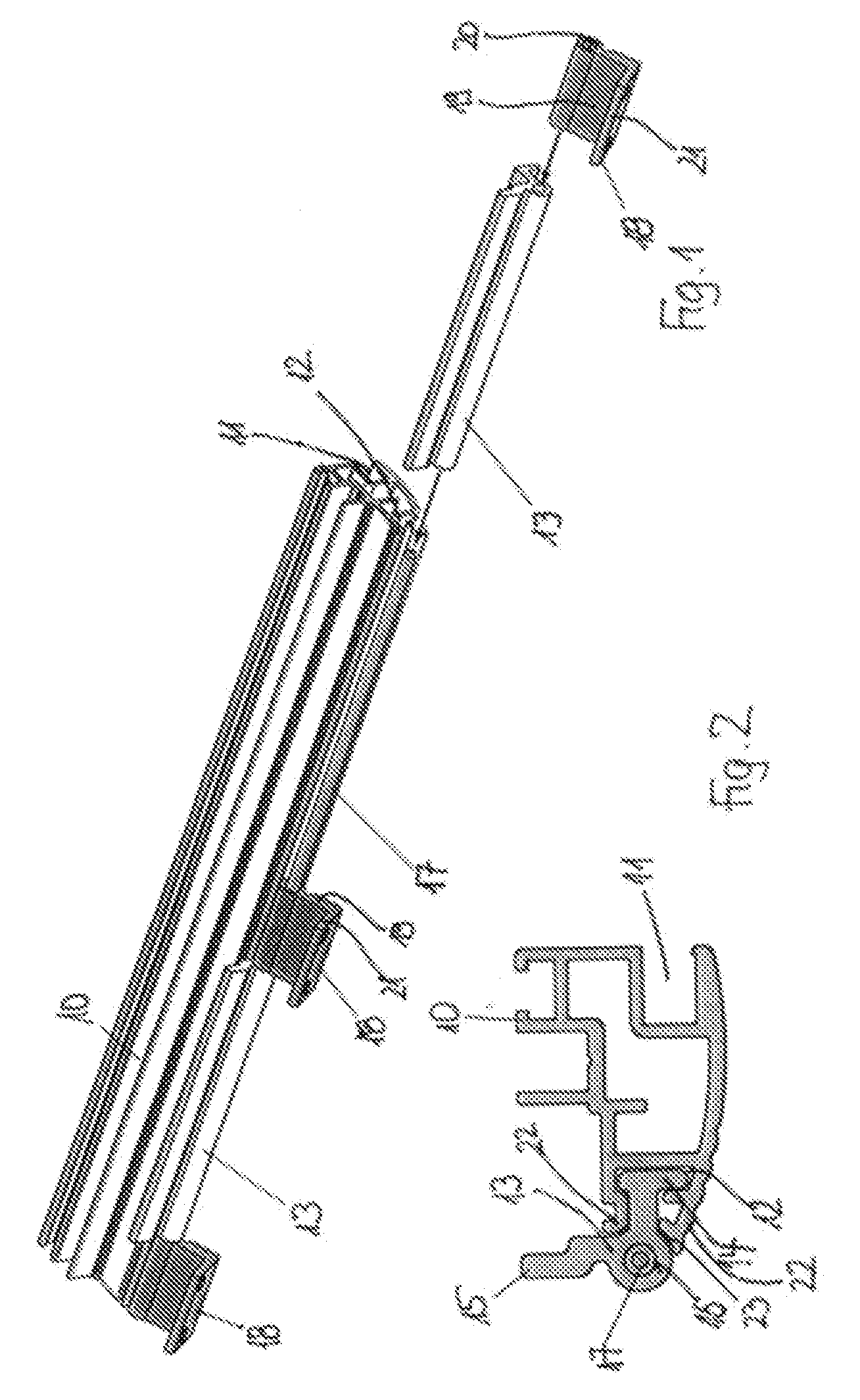
[0016]Referring now to the drawing in detail, as can be seen best in FIG. 2, the profiled frame member 10, which is used to form a profiled frame that forms a door or a window, is provided with a first profiled chamber 11 in which the panel, preferably a glass pane, can be placed and fixed in position. The profiled frame member 10 furthermore has an additional profiled chamber 12 into which can be inserted a molded element 13 that can accordingly be positively or interlockingly fixed in position on the profiled frame member 10. For this purpose, the molded element 13 has a profiled leg 14, the profiled shape of which corresponds to the shape of the additional profiled chamber 12 such that when the profiled leg 14 is inserted into the profiled chamber 12, it is fixed in position on the profiled frame member 10 without the need for further securement measures.

[0017]The molded element 13, which is fixed in position on the profiled frame member 10, has two legs, and in particular in add...


PUM


Abstract

A profiled frame, as a component of a window or door, for holding a plate-like panel supported in a circumferential frame, and comprising a profiled frame member having a profiled chamber that extends over at least a portion of the longitudinal length of the profiled frame member; molded elements to be inserted into, and positively held by, the profiled chamber; a hinge shaft for insertion through bores of the molded elements; and at least one monolithic hinge to be disposed between molded elements for mounting the profiled frame on a supporting component, wherein the hinge has a hinge bore via which the hinge can be threaded onto the hinge shaft, and wherein the hinge is fixed in position on the hinge shaft via adjoining molded elements.

Description

[0001]The instant application should be granted the priority date of Apr. 20, 2006 the filing date of the corresponding German patent application 10 2006 006 505.9.BACKGROUND OF THE INVENTION[0002]The present invention relates to a profiled frame, as a component of a window or door, for holding a plate-like panel supported in a circumferential frame, whereby at least one hinge is mounted on the profiled frame member of the profiled frame for mounting the window or door on a supporting component. The panel disposed on the profiled frame can be made of glass or also of some other suitable and if desired non-transparent material.[0003]Known windows or doors of circumferential profiled frames having variously configured profiled frame members have the drawback that for the mounting of hinges or hinge components on the profiled frame, the profiled frame member must at a later point in time be notched or recessed at the pertaining location that is provided for the hinge of the window or d...

Claims


Application Information

Patent Timeline
IPC IPC(8): E06B3/00
CPCE05D5/0238E05Y2900/132E05Y2900/148E06B2003/7046
Inventor HOFFMANN, RAINER
Owner EMKA BESCHLAGTAILE GMBH & CO KG
Learn More