
Two axis level

Inactive Publication Date: 2007-10-25
JELINEK DAVID
View PDF12 Cites 11 Cited by
  • Summary
  • Abstract
  • Description
  • Claims
  • Application Information

AI Technical Summary

Benefits of technology

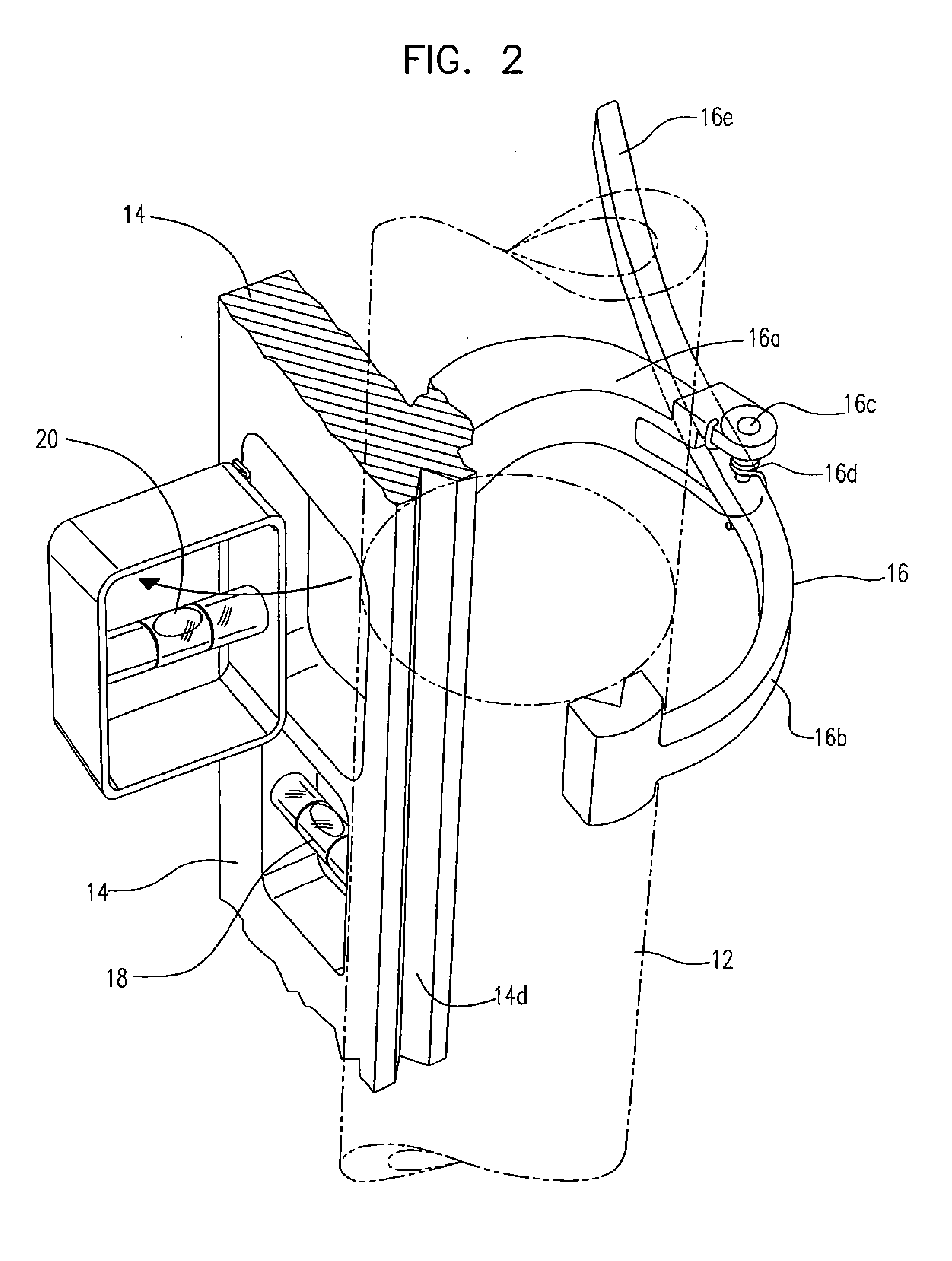
[0005] A level with two level indicators is provided. The indicators are mounted within a base perpendicular to each other, The perpendicularity of the first and second bubble level indicators provides a means for simultaneously observing whether a plane, perpendicular to a particular element in a structure, is horizontal. The first level indicator can be mounted in a convention manner in the base of the level, while the second level indicator can be arranged to be rotated outward from the body of the level to an orientation perpendicular to the first bubble indicator to provide the same planar capability. This arrangement minimizes the possibility of damage to the outwardly extending indicator, since it can be stored within the body of the level except during observation.

Problems solved by technology

This results either in an incorrect orientation of the element or repeated measurements of the two separate axes by a single level indicator to obtain the correct orientation.

Method used


Image

  • Two axis level
  • Two axis level
  • Two axis level

Examples


Embodiment Construction

[0010]FIG. 1 shows two axis plumbers level 10 attached to an essentially vertical element, here pipe 12. Base 14 is block shaped with opposed parallel sides mutually perpendicular to the other sides having axes 14a, 14b and 14c, as shown, which are aligned with one of the three mutually perpendicular sides. Linear concave recess 14d extending along one side of base 14 is aligned with axis 14c. Recess 14d is concave in shape and arranged to mate with at least the portion of the side of pipe 12, which is to be oriented vertically. With this arrangement placing recess 14d against pipe 12 will align axis 14a of base 14 with pipe 12. This results in horizontal axes 14a and 14b being in a plane which is perpendicular to pipe 12. As described later, the horizontal measurements are taken along axes 14a and 14b. With this arrangement locating level 10 correctly to measure a plane perpendicular to the pipe merely requires placing recess 14d of base 14 against pipe 12.

[0011] Base 14 can be he...


PUM


Abstract

Apparatus for measuring the verticality of a structural element uses two mutually perpendicular level indicators to determine the orientation of a plane with respect to level with a single observation. The indicators are mounted within a base which can have a recess along one side perpendicular to both level indicators. Placing the recess against the element to be measured at a predetermined location automatically aligns the observed plane with respect to the element. A spring loaded clamp can also be employed. The clamp can be separate or can be permanently attached to the base. The clamp engages the structural element and secures the apparatus to the element. One of the indicators can be pivoted from a first stored location within the base to a second orientation extending outward during observation to provide storage protection for the indicator.

Description

BACKGROUND OF THE INVENTION [0001] 1. Field of the Invention [0002] This invention provides apparatus to establish the orientation of vertical structures with respect to a horizontal plane to assist in their vertical installation using a single observation. [0003] 2. Description of the Related Art [0004] Installation of vertical elements often requires that some of the elements have a vertical orientation to conform to other elements of a structure. To establish vertical orientation two separate horizontal axis measurement are currently required. A common example is the installation of a vertical pipe. This will be described as an example although the same apparatus can be used with only minor modifications on any structural element which must be installed in a vertical orientation. Establishing vertical orientation of a pipe is presently accomplished by using a bubble level to establish each axis separately. Quite often after the first axis is measured, measuring the second axis wi...

Claims


Application Information

Patent Timeline
IPC IPC(8): G01C9/00
CPCG01C9/18
Inventor JELINEK, DAVID
Owner JELINEK DAVID
Learn More