
Storage Device, Memory Management Method and Program

a storage device and memory management technology, applied in the direction of memory adressing/allocation/relocation, instruments, input/output to record carriers, etc., can solve the problems of insufficient prevention of the occurrence of defective memory blocks, physical discontinuity of normal memory blocks, and suppress the efficiency of accessing flash memory, so as to achieve smooth access to storage areas and suppress the effect of reducing access efficiency

Inactive Publication Date: 2007-10-18
TOKYO ELECTRON DEVICE
View PDF9 Cites 34 Cited by
  • Summary
  • Abstract
  • Description
  • Claims
  • Application Information

AI Technical Summary

Benefits of technology

[0013] According to the aforementioned storage device, user data is written in units smaller than the block, thereby eliminating the need for an operation in which a new empty block (block in which no user data is stored) is searched and user data is written to the new empty block every time when user data is written. Then, data erasing to the block may not have to be performed at the time of writing user data. Moreover, processing for transferring an unchanged portion along with data writing is performed in units smaller than the block. Accordingly, a reduction in efficiency of access to the storage device can be suppressed.
[0034] Moreover, according to the present invention, it is possible to provide a storage device suitable for performing access to a storage area smoothly and a memory management method.

Problems solved by technology

In the flash memory, there is difficulty in insufficient prevention of occurrence of a defective memory block where data is not normally stored in the process of manufacture.
Accordingly, in some cases, arrangement of normal memory blocks becomes physically discontinuous due to defective memory blocks.
Then, the physical memory address is converted to the logical memory address, thereby suppressing a reduction in efficiency of access to the flash memory caused by discontinuous memory blocks.
For this reason, data erasing process with poor efficiency is frequently performed to rewrite the small amount of data, resulting in deterioration in efficiency of access to the memory.
Particularly, when an OS (Operating System) manages the storage contents of the flash memory in the same way as the case in which a hard disk device or a flexible disk manages the storage contents, efficiency of access to the flash memory worsens.
Since an amount of data in the FAT is generally extremely small as compared with the storage contents for one block, data erasing process with poor efficiency is frequently performed along with rewriting of FAT.
In the case where the storage contents of such the flash memory are managed by the aforementioned conventional method, data erasing process of a massive storage area is performed along with rewriting of the small amount of data, thereby causing deterioration in efficiency of access to the flash memory.
Accordingly, in general, the worse efficiency of data erasing process is, the more processing required to save data is increased, thereby preventing smooth access to the flash memory.
Particularly, regarding data erasing process of the flash memory with an extremely large storage capacity per block, an amount of data to be saved per one time is vastly increased, making it extremely difficult to perform smooth access to the flash memory.

Method used


Image

  • Storage Device, Memory Management Method and Program
  • Storage Device, Memory Management Method and Program
  • Storage Device, Memory Management Method and Program

Examples


Embodiment Construction

[0055] The following will explain an embodiment of the present invention using a storage system having a flash memory as an example with reference to the drawings.

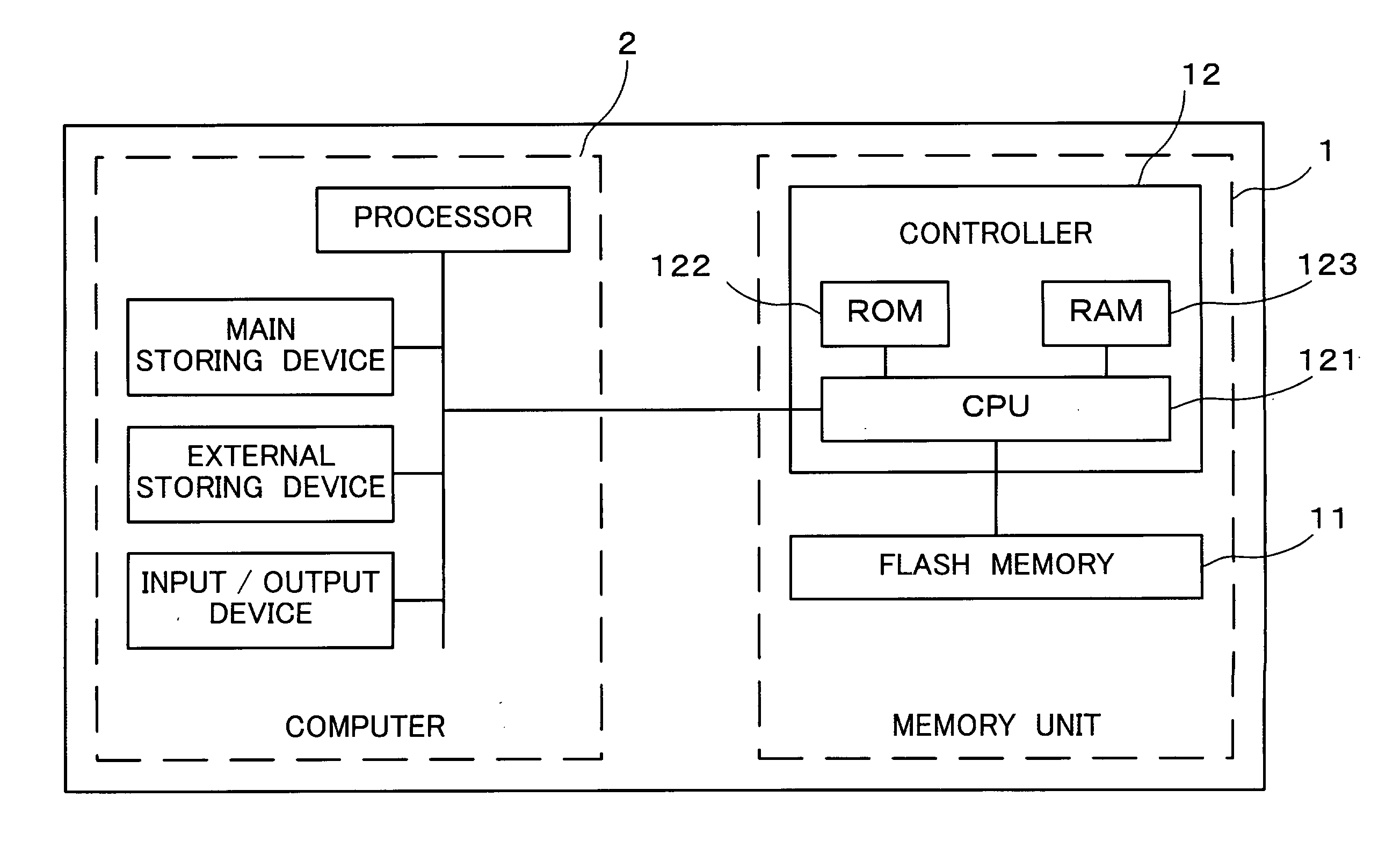
[0056]FIG. 1 is a block diagram illustrating a physical configuration of a storage system according to an embodiment of the present invention.

[0057] As illustrated in this figure, the storage system includes a memory unit 1 and a computer 2. The memory unit 1 is attached to the computer 2 via an internal bus which computer 2 has. Additionally, for example, as illustrated in FIG. 1, the memory unit 1 and the computer 2 may be incorporated into the same housing.

[0058] The memory unit 1 includes a flash memory 11 and a controller 12.

[0059] The flash memory 11 includes, for example, a storage device such as an EEPROM and a sequencer such as a logic circuit.

[0060] The flash memory 11 stores (writes) data supplied from the computer 2, reads stored data, supplies stored data to the computer 2, and erases stored data in respo...


PUM


Abstract

A physical group address is allocated to a storage area of a flash memory (11) for each group as units smaller than a block as units of data erasing, and the group includes multiple pages and the page includes multiple columns. When writing data and a logical address of a writing destination are supplied, a CPU (121) writes the data in a column in the group indicated by a writing pointer to associate the supplied logical address with the column. A relationship between the physical group address of the group having this column and the logical group address is stored in a logical / physical conversion table of a RAM (123). Data stored in the block is erased when the number of blocks having no empty block reaches a predetermined number or less.

Description

TECHNICAL FIELD [0001] The present invention relates to a storage device suitable for suppressing a reduction in access efficiency due to data erasing along with data rewriting, and relates to memory management method for managing a storage area of the storage device, and a program. BACKGROUND ART [0002] An EEPROM (Electrically Erasable / Programmable Read Only Memory) flash memory is used as a storage medium accessible (data readable / writable and erasable) by a computer. [0003] Data erase of the flash memory is performed on a basis of units of a storage capacity, which is called block. In the flash memory, there is difficulty in insufficient prevention of occurrence of a defective memory block where data is not normally stored in the process of manufacture. Accordingly, in some cases, arrangement of normal memory blocks becomes physically discontinuous due to defective memory blocks. International Publication No. WO99 / 30239 discloses a storage device that facilitates access to the me...

Claims


Application Information

Patent Timeline
Patent Type & Authority Applications(United States)
IPC IPC(8): G06F12/00
CPCG06F12/0246G06F3/06G06F3/08G06F12/00G06F12/02
Inventor KIKUCHI, SYUICHI
Owner TOKYO ELECTRON DEVICE
Learn More