
Systems and methods for optical actuation of microfluidics based on OPTO-electrowetting

a microfluidic and opto-electrowetting technology, applied in the field of manipulation or actuation of droplets in a microfluidic circuit, can solve the problems of difficult to switch in an array, large and expensive control electrode arrays, and large complexity of micro-machined pumps and valves

Active Publication Date: 2007-10-18
RGT UNIV OF CALIFORNIA
View PDF30 Cites 15 Cited by
  • Summary
  • Abstract
  • Description
  • Claims
  • Application Information

AI Technical Summary

Benefits of technology

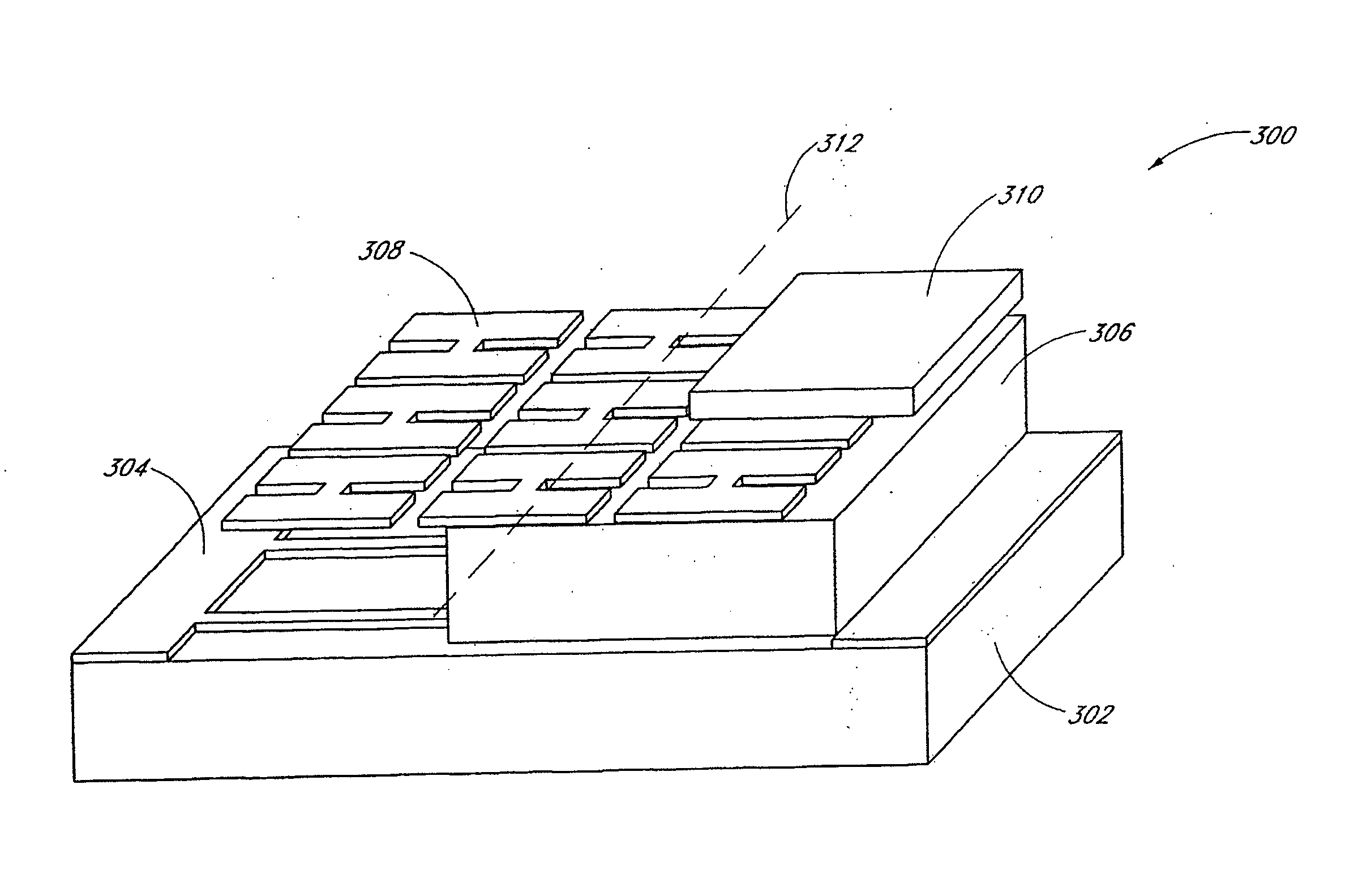
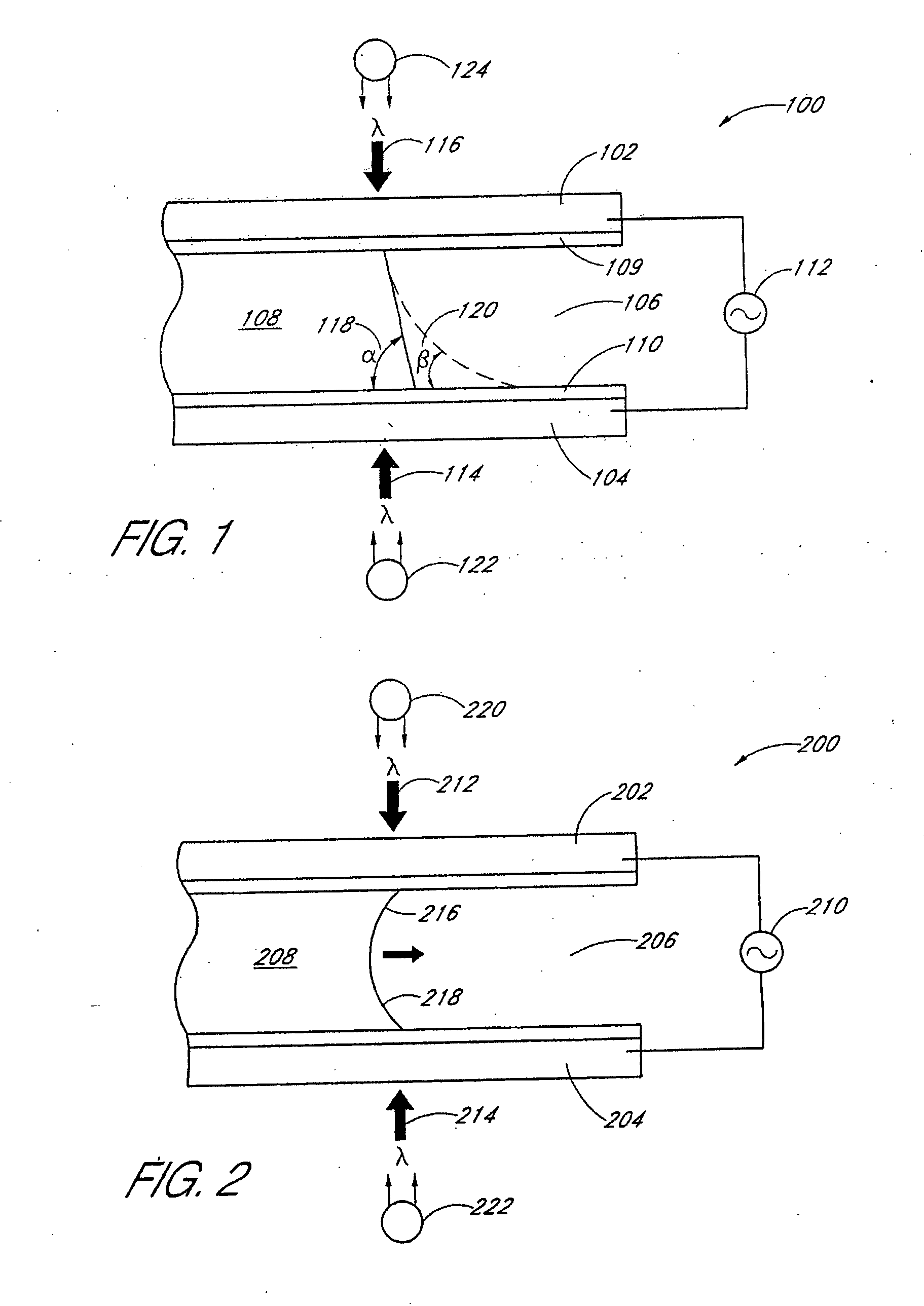
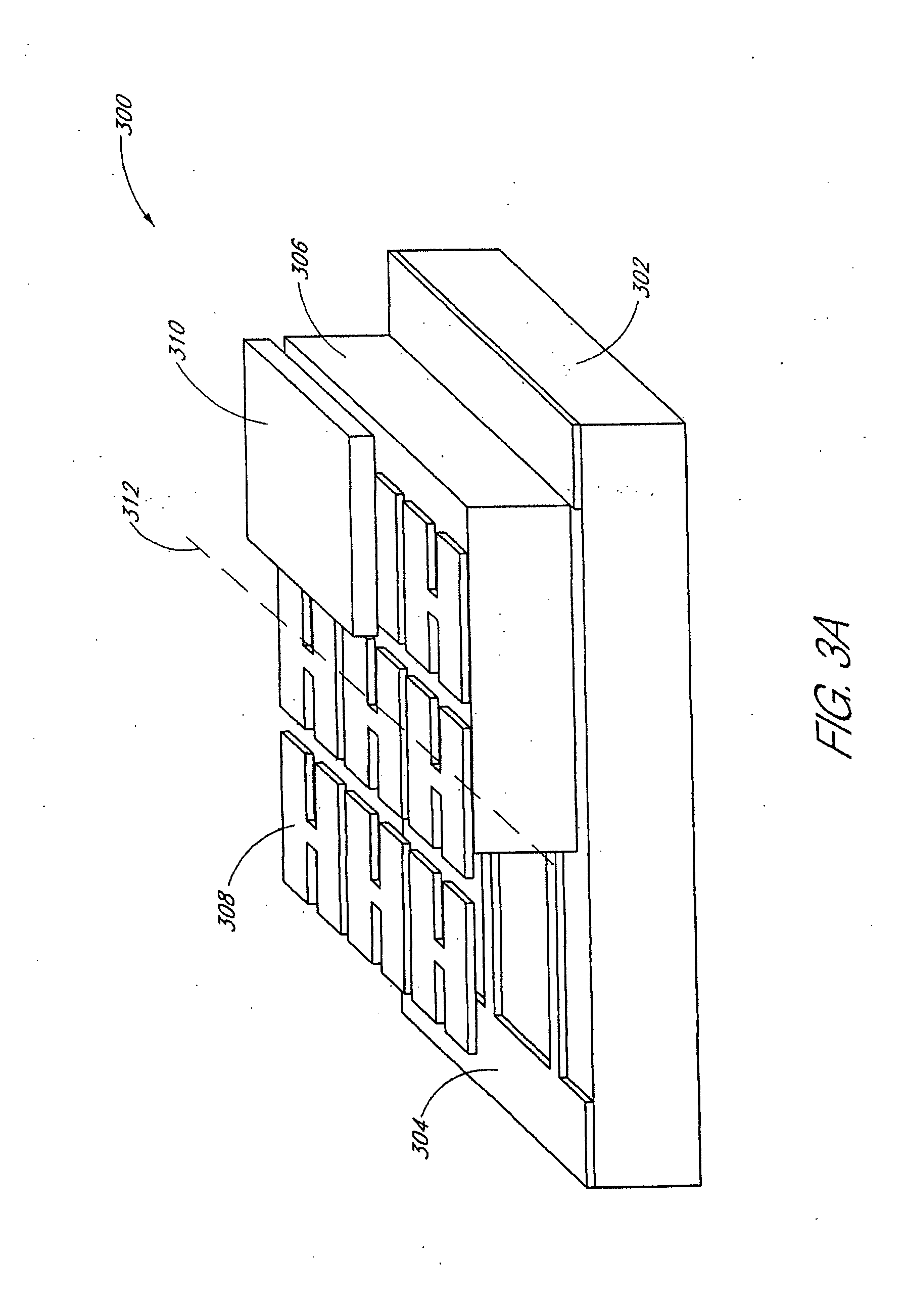
The invention is about manipulating droplets using optical techniques, such as electro-wetting, to perform various operations such as transporting, joining, cutting, and creating. The invention provides a microfluidic circuit with a first and second wall that hold a droplet in between and are responsive to light. The circuit includes an optical electro-wetting structure that selectively illuminates a portion of the walls to change the contact angle of the droplet and propel it using the electric field generated. The invention offers advantages over traditional pumps and valves, including the ability to manipulate droplets with light alone. It can be used in a microscale laboratory environment and can perform advanced laboratory operations without the need for complex machinery. The invention also allows for the simultaneous manipulation of multiple droplets and the ability to control the droplet's movement within a space defined between two electro-wetting surfaces.

Problems solved by technology

Conventional miniature laboratories can include relatively intricate, complex, and expensive micro-machined pumps and valves.
Disadvantageously, conventional electro-wetting techniques require relatively large and expensive control electrode arrays.
In addition, it may be desirable to utilize alternating current (AC) biasing, which can be relatively difficult to switch in an array.
As a result, conventional electro-wetting techniques are relatively expensive and can be cost-prohibitive in applications where large amounts of tests are conducted, and the miniature laboratory environments are discarded after a single use.
Moreover, the simultaneous control of multiple droplets using conventional electro-wetting techniques may not be achievable as a practical matter due to the impracticality of independently controlling a large number of AC biased electrodes.
Disadvantageously, such chemical reaction techniques can take on the order of minutes to react and are too slow for practical use.
In addition, at least one such technique cannot manipulate water droplets.
Disadvantageously, ultraviolet light is used to generate the chemical reaction.
Ultraviolet light can be harmful to biological organisms.
Further disadvantageously, the chemical reaction is slow and may require at least 20 minutes to occur.
Thus, while such chemical reaction techniques may be applicable to “anti-fogging glass and self-cleaning construction materials,” see Sun, et al., such chemical techniques may be ill suited to laboratory environments.

Method used


Image

  • Systems and methods for optical actuation of microfluidics based on OPTO-electrowetting
  • Systems and methods for optical actuation of microfluidics based on OPTO-electrowetting
  • Systems and methods for optical actuation of microfluidics based on OPTO-electrowetting

Examples


Embodiment Construction

[0030] Although this invention will be described in terms of certain preferred embodiments, other embodiments that are apparent to those of ordinary skill in the art, including embodiments that do not provide all of the benefits and features set forth herein, are also within the scope of this invention. Accordingly, the scope of the invention is defined only by reference to the appended claims.

[0031] Embodiments of the invention advantageously provide the manipulation or actuation of droplets in a microfluidic circuit that can be relatively inexpensively produced. Embodiments of the invention manipulate droplets by controlling the electro-wetting characteristics of a surface with light, thereby inducing a gradient in the surface tension of a droplet. The gradient in the surface tension propels the droplet by capillary force.

[0032] Embodiments of the invention thereby permit the manipulation of droplets without relatively intricate and expensive micro-mechanical devices, such as mi...


PUM

PropertyMeasurementUnit
frequencyaaaaaaaaaa
frequencyaaaaaaaaaa
wavelengthaaaaaaaaaa

Abstract

The invention is related to methods and apparatus that manipulate droplets in a microfluidic environment. Advantageously, embodiments of the invention manipulate droplets by controlling the electro-wetting characteristics of a surface with light, thereby inducing a gradient in the surface tension of a droplet. The gradient in the surface tension propels the droplet by capillary force. A variety of operations, such as transporting, joining, cutting, and creating can be performed. Advantageously, embodiments of the invention obviate the need to create a relatively large and complex control electrode array. A plurality of photoconductive cells or a layer of a photoconductive material selectively couples an electrode carrying an electrical bias to otherwise floating conductive cells in response to a beam of light. The electrical bias applied to the conductive cell generates a localized electric field, which can change the contact angle of the droplet, thereby permitting the droplet to be propelled.

Description

GOVERNMENT RIGHTS [0001] This invention was made with Government support under Contract Number MDA972-00-1-0019 awarded by DARPA. The Government has certain rights in the invention.BACKGROUND OF THE INVENTION [0002] 1. Field of the Invention [0003] The invention generally relates to the manipulation of droplets. In particular, the invention relates to the manipulation or actuation of droplets in a microfluidic circuit. [0004] 2. Description of the Related Art [0005] The handling of liquids is fundamental to many fields in science, such as biology and chemistry. To efficiently perform relatively large numbers of tests, miniature laboratory environments have been produced. Conventional miniature laboratories can include relatively intricate, complex, and expensive micro-machined pumps and valves. [0006] One known technique which appears to eliminate the need for micro-machined pumps and valves actuates droplets by electro-wetting. See Cho, S., et al, “Towards Digital Microfluidic Circ...

Claims


Application Information

Patent Timeline
Patent Type & Authority Applications(United States)
IPC IPC(8): B01L3/02G01N37/00B01J19/12B01L3/00F04B19/00G01N35/10
CPCB01L3/502792B01L2300/089B01L2400/0415Y10T436/2575F04B19/006G01N2035/1034B01L2400/0427
Inventor CHIOU, PEI YUWU, MING C.
Owner RGT UNIV OF CALIFORNIA
Learn More