Forming Method of Dynamic Pressure Generating Portion and Fluid Dynamic Bearing Device

a technology of dynamic pressure generating portion and fluid dynamic bearing, which is applied in the direction of bearings, shafts and bearings, dynamo-electric machines, etc., can solve the problems of deterioration of groove patterns, process too complicated to perform rationalization, and non-printed portions, and achieve high-precision dynamic pressure generating portions and low cost. , the effect of low cos

Inactive Publication Date: 2007-10-18
NTN CORP
View PDF1 Cites 7 Cited by
  • Summary
  • Abstract
  • Description
  • Claims
  • Application Information

AI Technical Summary

Benefits of technology

[0050] As described above, according to the present invention, the process for etching the dynamic pressure generating portion and the process for removing the hardened ink can be omitted. Thus, the dynamic pressure generating portion can be formed at a low cost. Therefore, a fluid dynamic bearing device including the highly accurate dynamic pressure generating portion can be obtained at a low cost.
[0051] Moreover, according to the present invention, the dynamic pressure generating portion is formed from the resin composition that has excellent oil resistance. Thus, wear of the surface of the dynamic pressure generating portion can be suppressed. Therefore, the bearing performance can be kept stable over a long period of time and the durability thereof can be improved.
[0052] By forming the dynamic pressure generating portion from a thermosetting ink, the cycle time when the dynamic pressure generating portion is formed can be reduced, thereby reducing the cost. In addition, the dynamic pressure generating portion can be formed with high accuracy.

Problems solved by technology

Then, non-printed portions are caused to corrode by etching, thereby forming the dynamic pressure generating grooves.
However, in the method (1), the process is too complicated to perform rationalization.
This easily causes deterioration of the groove pattern.
Thus, wear can easily occur at the contact portion.
Therefore, there is concern that the printing accuracy is lowered because of the wear, deformation, and the like of the printing mold in case of mass production.
Thus, it is difficult to deal with a wide variety of demands in recent years.
This increases the used amount of the corrosion-resistant ink that is expensive and therefore the method (3) is not economical.
Furthermore, after the printing, corrosion of the unprinted portion by etching and removal of the ink are essential.
Therefore, the forming process is complicated and contains multiple steps, thus increasing the cost.
However, in case of machining, it is difficult to form the dynamic pressure generating grooves with high accuracy.
Moreover, this method is not economical.
Thus, before a curing action by ultraviolet rays takes place around the interface between the ink and the shaft member, an adhesive state at that interface is unstable.
Therefore, under a certain printing condition or for some specifications of a bearing device, the ink may peel off or fall during the printing or a later process.
The separation or falling of the ink deteriorates the accuracy of the dynamic pressure generating portion and lowers the rotational accuracy of the fluid dynamic bearing device.

Method used


Image

  • Forming Method of Dynamic Pressure Generating Portion and Fluid Dynamic Bearing Device
  • Forming Method of Dynamic Pressure Generating Portion and Fluid Dynamic Bearing Device
  • Forming Method of Dynamic Pressure Generating Portion and Fluid Dynamic Bearing Device

Examples


Embodiment Construction

[0064] Embodiments of the present invention are now described with reference to the drawings.

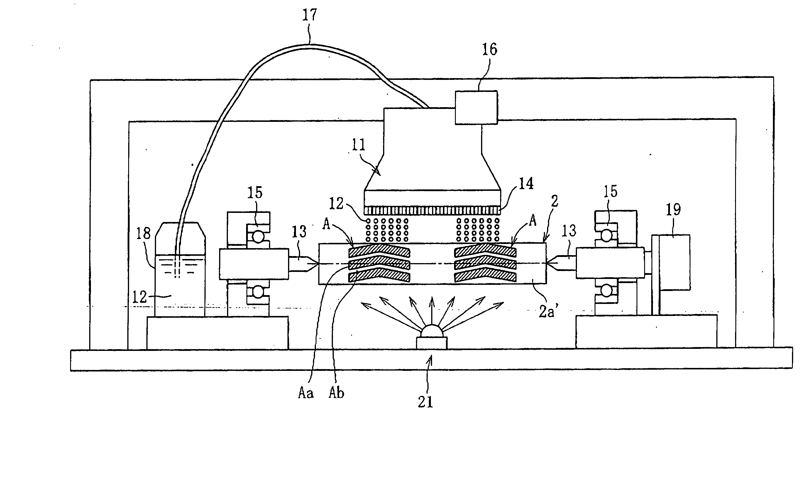
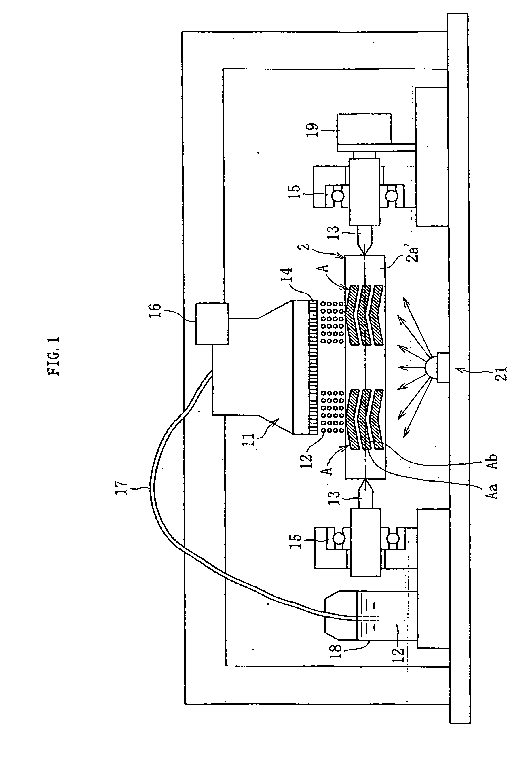
[0065]FIG. 1 generally shows an ink-jet type forming device as an exemplary forming device for forming a dynamic pressure generating portion according to the present invention. In this forming device, a material 2a′ of a shaft member 2 is supported transversely by shaft-like holding portions 13 that are pressed against the material 2a′ on respective sides. The two holding portions 13 are rotatably supported by roller bearings 15, respectively. One of the holding portions 13 is connected to a rotary drive portion 19 formed by a motor or the like. When the rotary drive portion 19 is actuated, the material 2a′ receives a rotary power through the holding portion 13 and rotates.

[0066] The material 2a′ is formed of metal such as stainless steel and is in a shaft shape. One or more nozzle heads 11 and a light source 21 are arranged around an outer circumference of the material 2a′. In the present...


PUM


Abstract

The present invention aims to make it possible to form a dynamic pressure generating portion by a simple process with high accuracy at a low cost. In order to achieve the object, in the present invention the dynamic pressure generating portion A is formed by the step of supplying a small amount of an ink 12 onto a surface of a material 2a′ to print the dynamic pressure generating portion A for generating a dynamic pressure of fluid in a bearing gap with an aggregate of the ink, and the step of hardening the ink 12.

Description

TECHNICAL FIELD [0001] The present invention relates to a method for forming a dynamic pressure generating portion on a material, and also relates to a fluid dynamic bearing device including this dynamic pressure generating portion. BACKGROUND ART [0002] A dynamic bearing generates a pressure by using a dynamic pressure action of fluid caused by relative rotation of a shaft member and a bearing sleeve in a bearing gap, and supports the shaft member in a non-contact manner by the thus generated pressure. The dynamic bearing has features of high-speed rotation, high rotational accuracy, low noise, and the like. In recent years, by bringing the features into play, applications of the dynamic bearing have expanded. For example, the dynamic bearing can be used as a bearing for a spindle motor used in information equipment, e.g., a magnetic disc device such as HDD or FDD, an optical disc device such as CD-ROM, CD-R / RW, or DVD-ROM / RAM, and a magnetooptical device such as MD or MO, a bearin...

Claims


Application Information

Patent Timeline
Patent Type & Authority Applications(United States)
IPC IPC(8): F16C32/06F16C33/10H02K5/167
CPCF16C17/026H02K5/1675F16C33/107F16C17/107
Inventor NAKAJIMA, TATSUONAKAJIMA, RYOUICHIKOMORI, ISAO
Owner NTN CORP
Why Eureka
Try Eureka