
Transmitting apparatus and method, receiving apparatus and method, program and recording medium, and transmitting/receiving system

Inactive Publication Date: 2007-10-18
SONY CORP
View PDF27 Cites 28 Cited by
  • Summary
  • Abstract
  • Description
  • Claims
  • Application Information

AI Technical Summary

Benefits of technology

[0013] The present invention is made in view of the above-described circumstances, and it is an object of the present invention to enable acquisition of high quality data even if the amount of data is small when it is transmitted. In other words, the present invention is intended to suppress deterioration in data quality while reducing transmission data.
[0014] It is another object of the present invention to reduce the amount of encoded data.
[0035] According to the present invention, the amount of encoded data can be reduced, and the encoded data reduced in volume can be decoded with good precision.
[0040] According to the present invention, the amount of encoded data can be reduced.
[0045] According to the present invention, encoded data reduced in volume can be decoded with good precision.

Problems solved by technology

Thus, it is difficult for the receiving PDA to obtain an image having high quality.
Also, in wireless communication, lack of partial transmission data, such as packets, easily occurs, and in this case, in the receiving PDA, the quality of the image more deteriorates.
Thus, in some cases, it is difficult to reduce the amount of the encoded data.

Method used


Image

  • Transmitting apparatus and method, receiving apparatus and method, program and recording medium, and transmitting/receiving system
  • Transmitting apparatus and method, receiving apparatus and method, program and recording medium, and transmitting/receiving system
  • Transmitting apparatus and method, receiving apparatus and method, program and recording medium, and transmitting/receiving system

Examples


Embodiment Construction

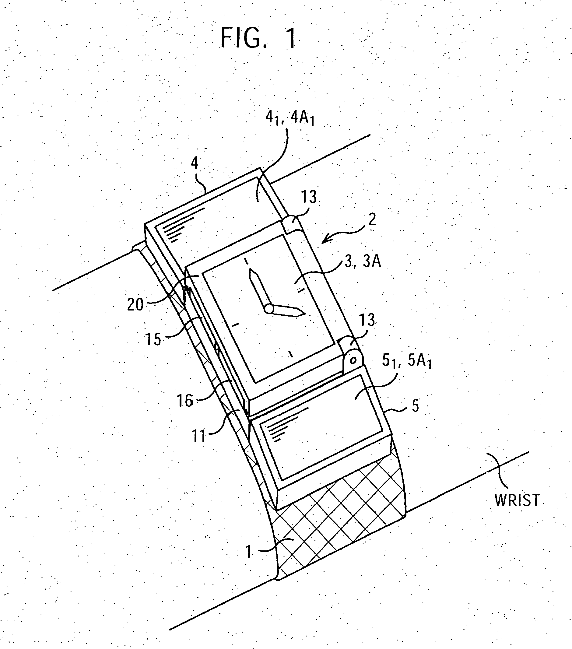
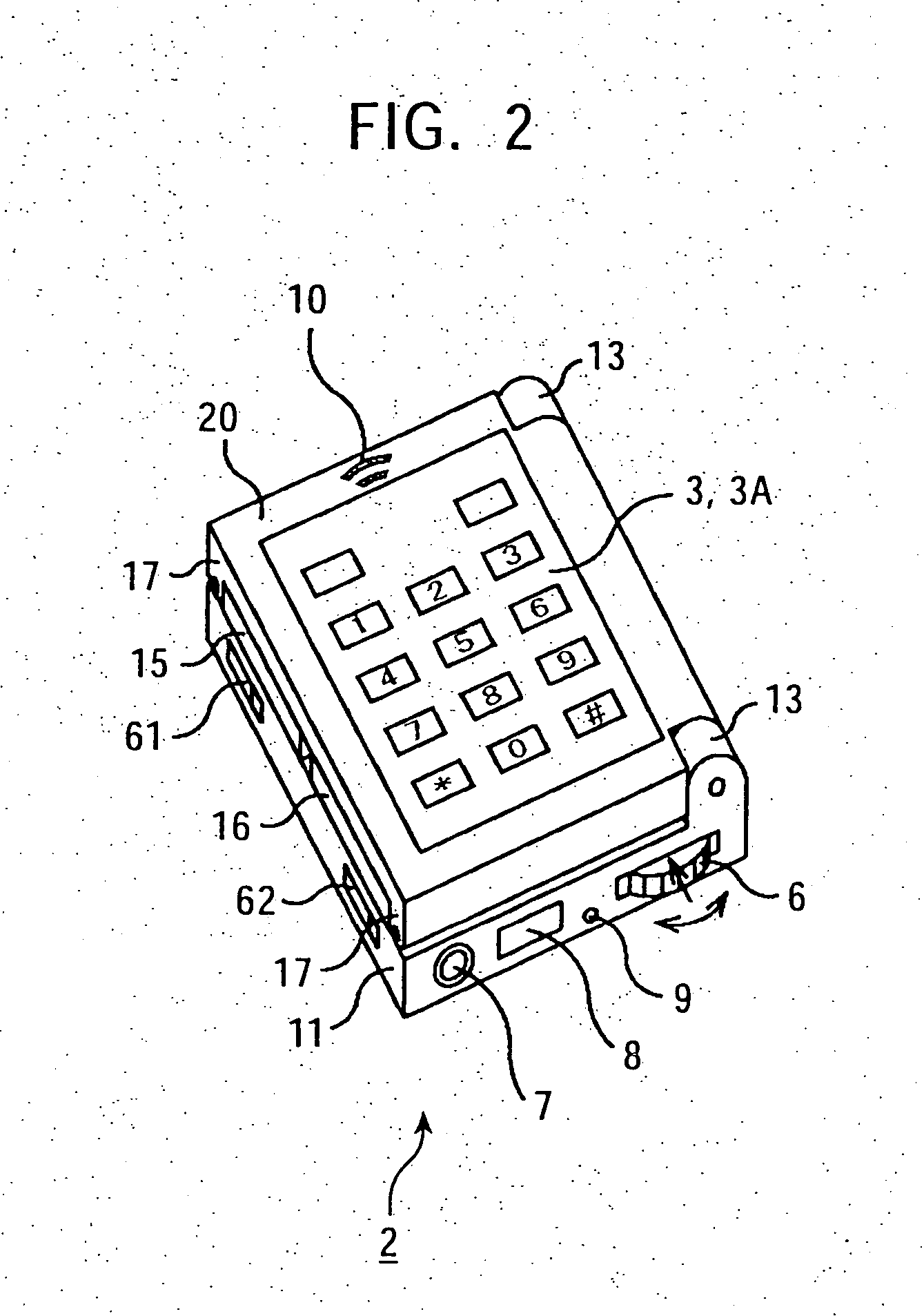
[0116] FIGS. 1 to 4 show the exterior of a PDA according to an embodiment of the present invention.

[0117] As shown in FIG. 1, the PDA is of a watch type, and has a structure in which a watch bracelet is provided with a main block 2. A user easily carries the PDA by wearing the watch bracelet 1 on the right or left wrist similarly to wearing a watch.

[0118] The main block 2 corresponds to a main unit in the case of a watch, and consists of a main unit 11 and a cover unit 20 which is rotatably joined to an end of the main unit 11.

[0119] The cover unit 20 has a liquid crystal display (LCD) 3 provided so as to be exposed on its top surface when it is closed. In the embodiment in FIG. 1, the LCD 3 displays a screen of a watch having the hour hand and the minute hand.

[0120] Also, as shown in FIG. 1 or 4, side panels 4 and 5 are provided on the upper and lower sides of the main block 2 on the watch bracelet 1 of the PDA. In the side panel 4, an LCD 41 is provided so as to be upwardly ex...


PUM


Abstract

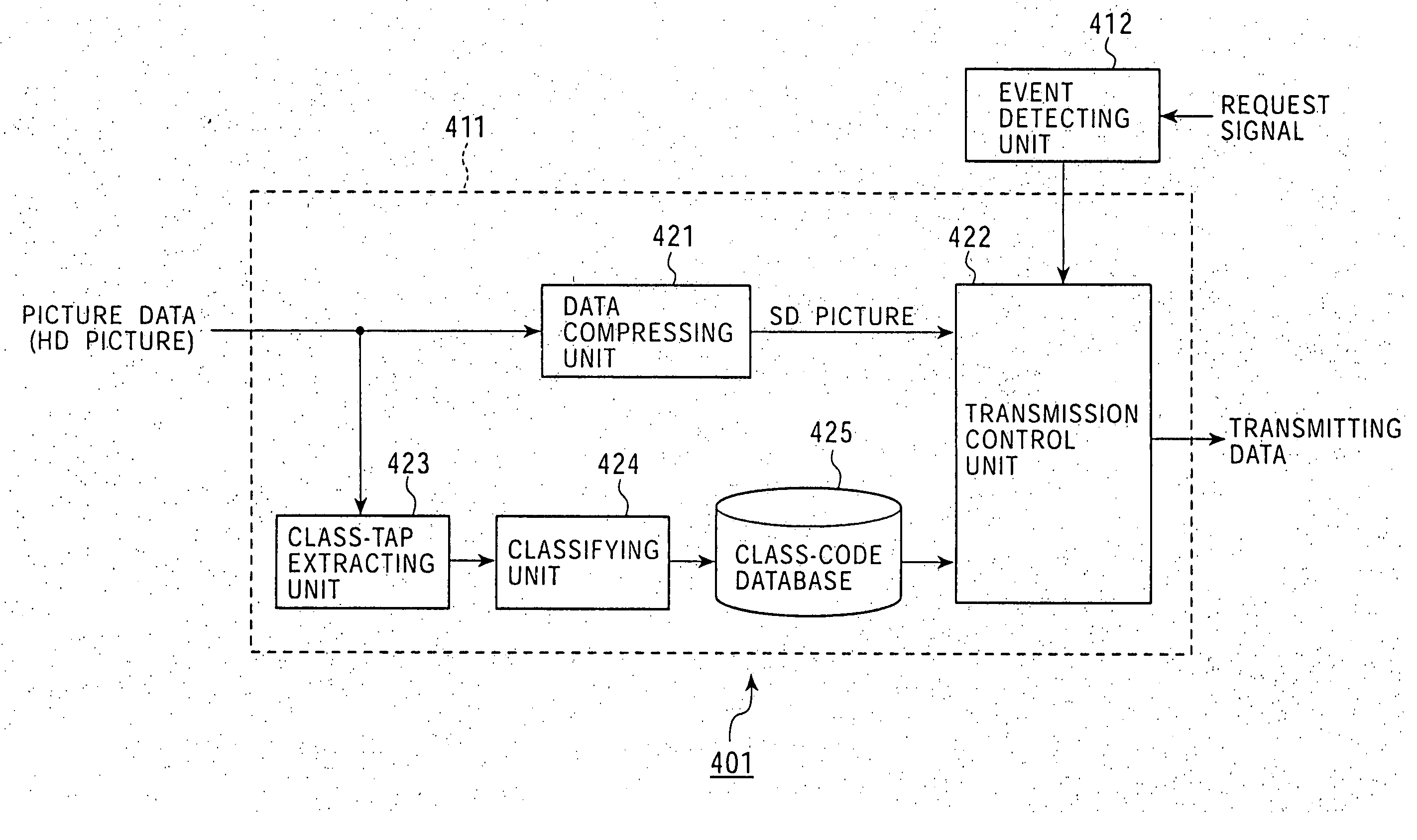
A receiving processing unit receives identical SD pictures transmitted a plurality of number of times, and performs addition for weighting an SD picture stored in a storage and the received SD pictures. The receiving processing unit stores the obtained values as a new SD picture in the storage. A picture-quality determining unit determines the picture quality of the new SD picture stored in the storage, and based on the determined picture quality, a request-signal transmitting unit requests class codes representing classes obtained by classifying the pixels of an HD picture in which the quality of an SD picture is increased. A receiving-control unit receives class codes which are transmitted in response to the request, and based on the SD picture and the class codes, an adaptive processing unit calculates predicted values of an HD picture corresponding to the SD picture.

Description

BACKGROUND OF THE INVENTION [0001] 1. Field of the Invention [0002] The present invention relates to transmitting apparatuses and methods, receiving apparatuses and methods, programs and recording media used therewith, and transmitting / receiving systems, and in particular, to a transmitting apparatus and method, and a receiving apparatus and method, a program and a recording medium (which are used therewith), and a transmitting / receiving system in which high quality data can be obtained by using, for example, data (information) stored from the past. [0003] In addition, the present invention relates to data processing systems, encoding apparatuses and methods, decoding apparatuses and methods, and programs and recording media used therewith, and in particular, to a data processing system, an encoding apparatus and method, a decoding apparatus and method, a program, and a recording medium which are used for reducing the amount of encoded data obtained by performing vector quantization...

Claims


Application Information

Patent Timeline
IPC IPC(8): H04L27/00H03K9/00G06F17/00G06F1/16G06F3/023G06F3/14G06F11/00G06F13/00G06F15/00G06F17/16G06T9/00H03M11/00H04B7/00H04LH04L27/04H04L29/10H04N7/24H04N19/895H04N21/2343H04N21/414H04N21/44H04N21/4402H04N21/4788H04N21/658
CPCG06F1/1616H04N19/895G06F1/163G06F1/1632G06F1/1641G06F1/1647G06F1/1679G06F1/1683G06F1/1692H04N21/234327H04N21/41407H04N21/44008H04N21/440227H04N21/4788H04N21/658H04N19/503H04N19/172H04N19/103H04N19/154H04N19/162H04N19/98H04N19/94G06F1/1626G06F1/1613
Inventor KONDO, TETSUJIRO
Owner SONY CORP
Learn More