Heatsink and heatsink-positioning system

Active Publication Date: 2007-10-18
ADVANCED SEMICON ENG INC
View PDF29 Cites 4 Cited by
  • Summary
  • Abstract
  • Description
  • Claims
  • Application Information

AI Technical Summary

Benefits of technology

[0009]Since the ring-shaped sidewall of the heatsink of the invention has a plurality of first positioning portion and the positioning device has a plurality of second positioning portions corresponding to the first positioning portions respectively, the second positioning portions can firmly fix the first positioning portions, so that the problem of displacement of the heatsink can be improved.

Problems solved by technology

Point-contact is a very unstable fixing method, so the heatsink 10 may rotate and then shift.
Therefore, the fixing position will be unstable or fail.

Method used


Image

  • Heatsink and heatsink-positioning system
  • Heatsink and heatsink-positioning system
  • Heatsink and heatsink-positioning system

Examples


Embodiment Construction

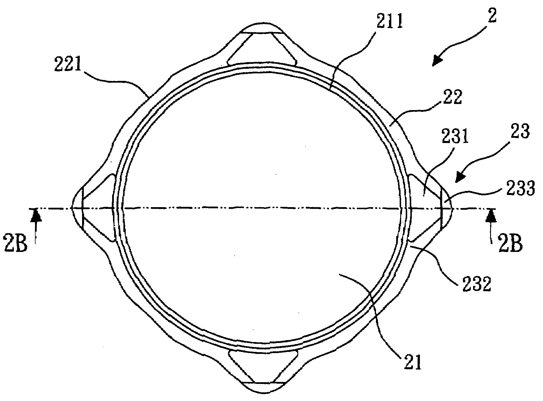
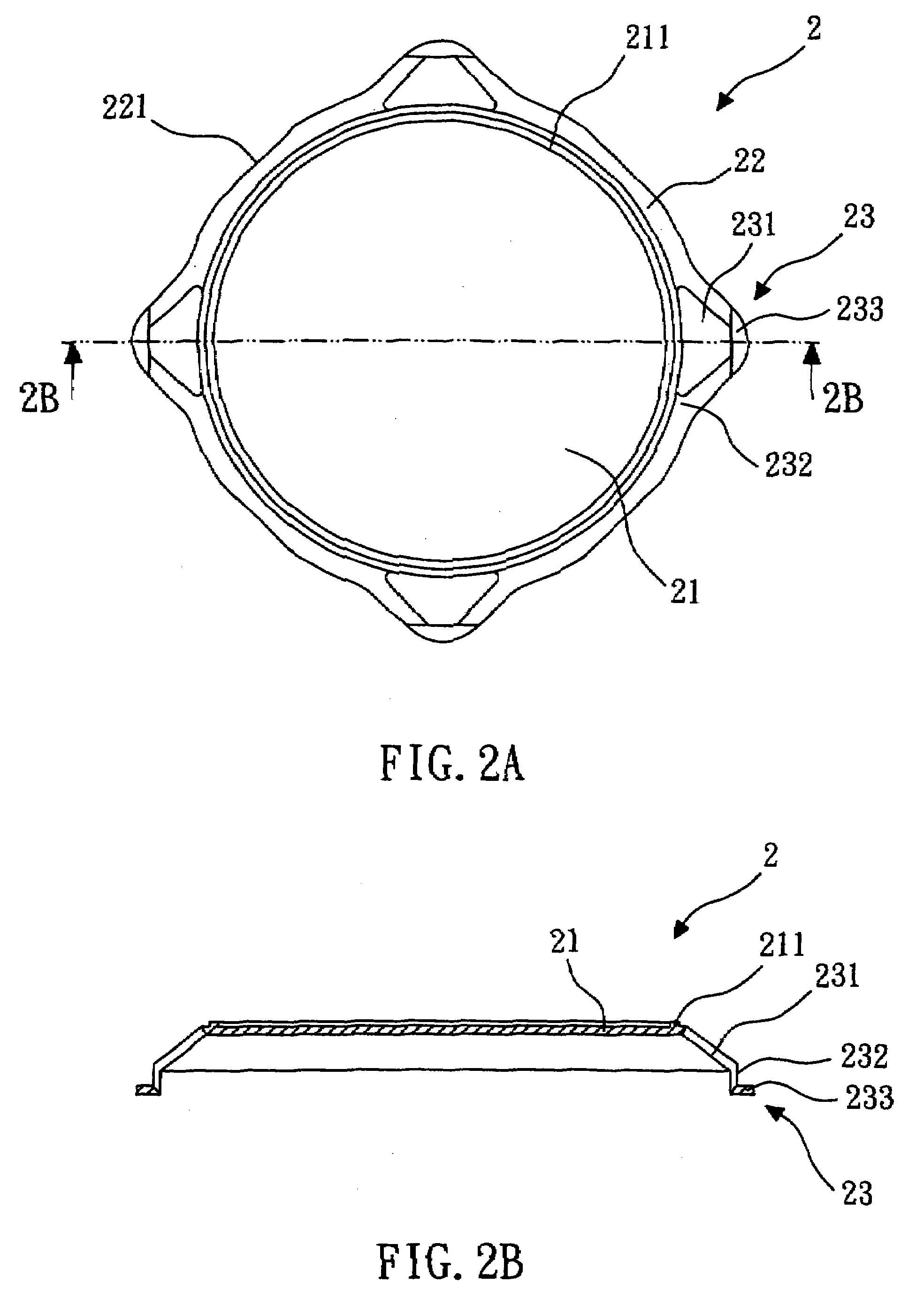
[0016]Referring to FIG. 2A and FIG. 2B, they show a heatsink according to a first embodiment of the present invention, wherein FIG. 2B shows the structure of a sectional view along the line 2B-2B in FIG. 2A. The heatsink 2 of the first embodiment comprises a circular top 21, a ring-shaped sidewall 22 and a plurality of foot portions 23. The circular top 21 has a ring-shaped protrusion 211 formed on the circular top 21 and near the edge of the circular top 21. The ring-shaped protrusion 211 can avoid the encapsulating compound bleeding and covering the circular top 21, so that the heat dissipation efficiency of the heatsink 2 will not be decreased. The ring-shaped sidewall 22 connects to the circular top 21 and extends away from the circular top 21. The ring-shaped sidewall 22 and the circular top 21 form a hat-shaped structure. The ring-shaped sidewall 22 has a plurality of first positioning portions 221. The first positioning portions 221 are planes and are used for fixing the heat...


PUM


Abstract

The present invention relates to a heatsink and a heatsink-positioning system. The heatsink-positioning system comprises a heatsink and a positioning device. The heatsink comprises a circular top, a ring-shaped sidewall and a plurality of foot portions. The ring-shaped sidewall connects to the circular top and extends away from the circular top. The ring-shaped sidewall has at least one first positioning portion used for fixing the heatsink. The foot portions connect to the ring-shaped sidewall and extend away from the ring-shaped sidewall. Each foot portion has an opening. The positioning device has at least one second positioning portion corresponding to the first positioning portion and is used for fixing the first positioning portion. By utilizing the heatsink-positioning system of the invention, the problem of displacement of the heatsink can be improved.

Description

BACKGROUND OF THE INVENTION[0001]1. Field of the Invention[0002]The invention relates to a heatsink and a heatsink-positioning system, particularly to a positioning system having a plurality of positioning portions for positioning a heatsink.[0003]2. Description of the Related Art[0004]Referring to FIG. 1, it shows a conventional heatsink-positioning system. The heatsink-positioning system 1 comprises a heatsink 10 and a positioning device 11. The heatsink 10 has a plurality of foot portions 101 and a top surface 102. The positioning device 11 has a fixing surface 111. The fixing surface 111 is a plane and is used for fixing the heatsink 10.[0005]Since the top surface 102 of the conventional heatsink 10 is circular and the fixing surface 111 is a plane, the positioning device 11 can just contact the heatsink 10 by point-contact. Point-contact is a very unstable fixing method, so the heatsink 10 may rotate and then shift. Therefore, the fixing position will be unstable or fail.[0006]...

Claims


Application Information

Patent Timeline
IPC IPC(8): F28F9/00F28F7/00
CPCF28D2021/0029H01L23/04H01L23/3672H01L23/3675H01L2924/0002H01L2924/00
Inventor LIU, JUN-CHENGLIU, CHENG-CHENG
Owner ADVANCED SEMICON ENG INC
Why Eureka
Try Eureka