
Method and apparatus for continuous or batch optical fiber preform and optical fiber production

a technology of optical fiber and preform, applied in glass fiber drawing apparatus, glass making apparatus, manufacturing tools, etc., can solve the problems of complex couplings, low deposition rate, limited cable length, etc., and achieve the effect of enhancing deposition efficiency and reducing losses

Inactive Publication Date: 2007-10-18
BROWN DAVID P
View PDF7 Cites 7 Cited by
  • Summary
  • Abstract
  • Description
  • Claims
  • Application Information

AI Technical Summary

Benefits of technology

[0019] This invention allows high deposition efficiencies of matrix material and dopants, high uniformity of dopants in the preform and can be easily integrated into existing preform and fiber drawing facilities. Various forces can be used according to the invention to enhance deposition including thermophoretic, inertial, electrophoretic, photophoretic, acoustic and / or gravitational.

Problems solved by technology

Such methods are able produce high quality single or multimode optical fiber in which the refractive index can be varied across the fiber radius, however, the cable length is limited by the discontinuous nature of the production process and deposition rates are low.
This leads to complex couplings (e.g. U.S. Pat. No. 4,997,797) and associated losses and disruptions in light transfer.
Moreover, the methods described produce a coating composed of nucleated particles having a wide distribution of size and morphology which can further reduce transmission efficiency.

Method used


Image

  • Method and apparatus for continuous or batch optical fiber preform and optical fiber production
  • Method and apparatus for continuous or batch optical fiber preform and optical fiber production
  • Method and apparatus for continuous or batch optical fiber preform and optical fiber production

Examples


Embodiment Construction

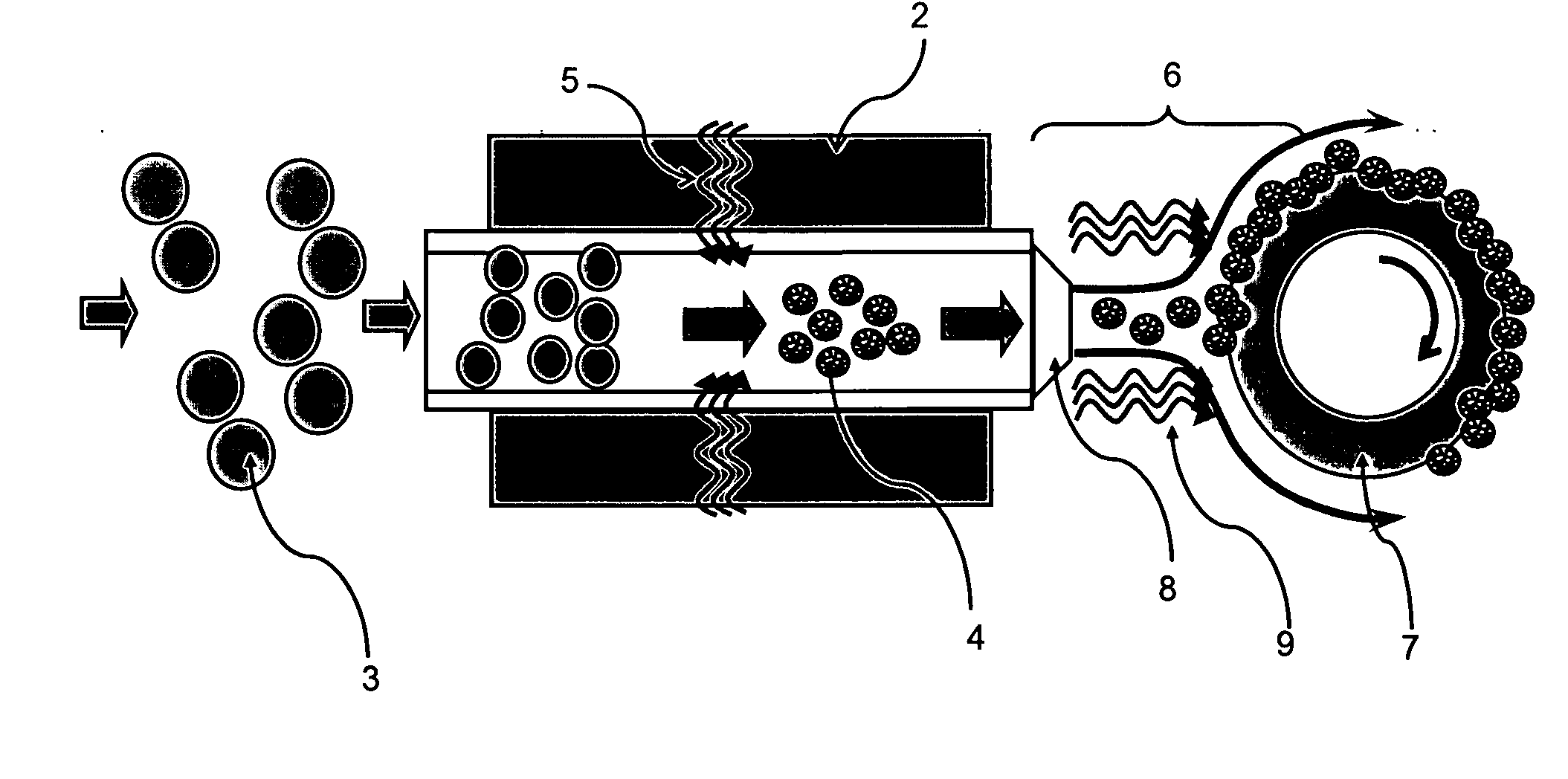
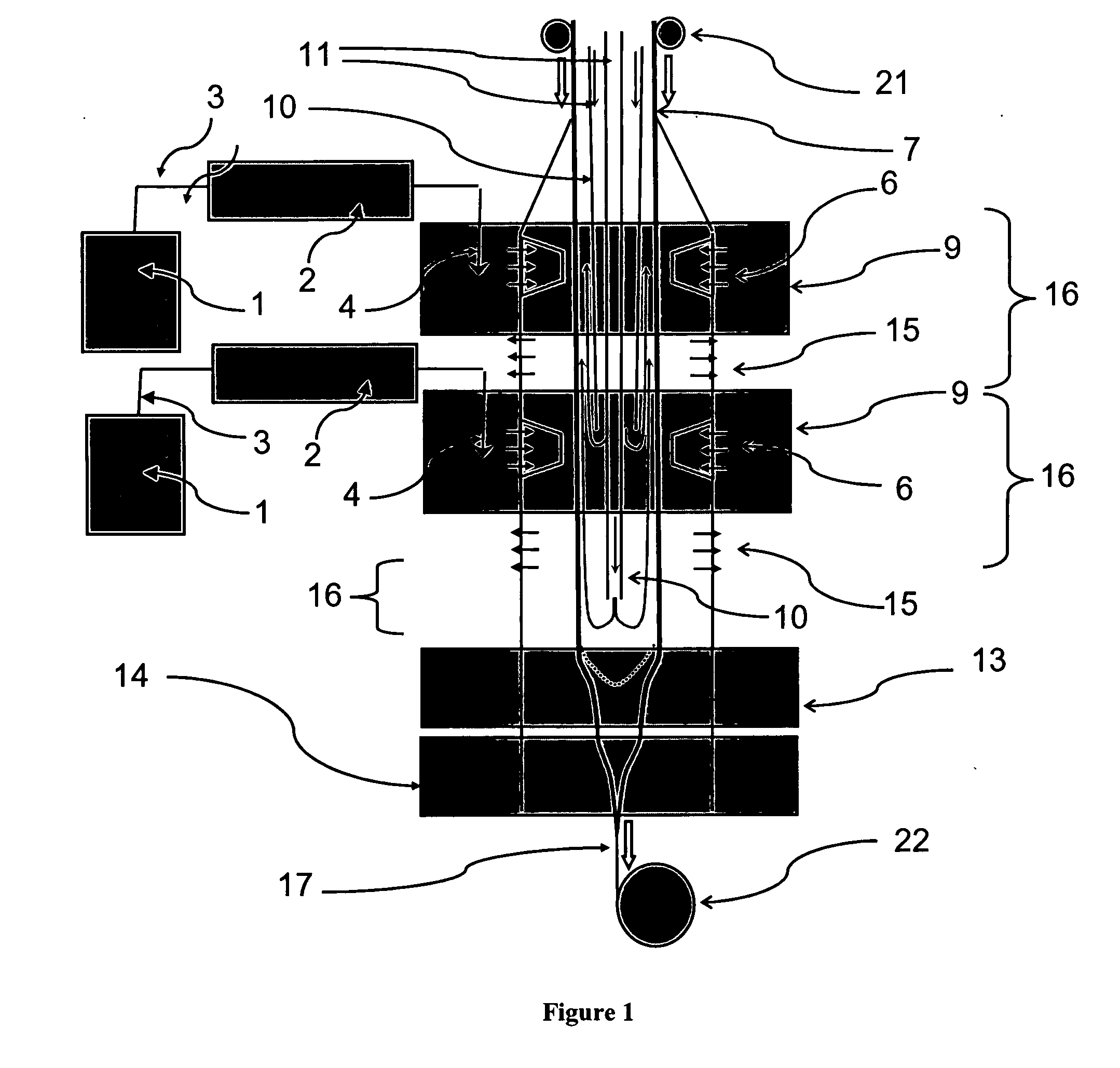
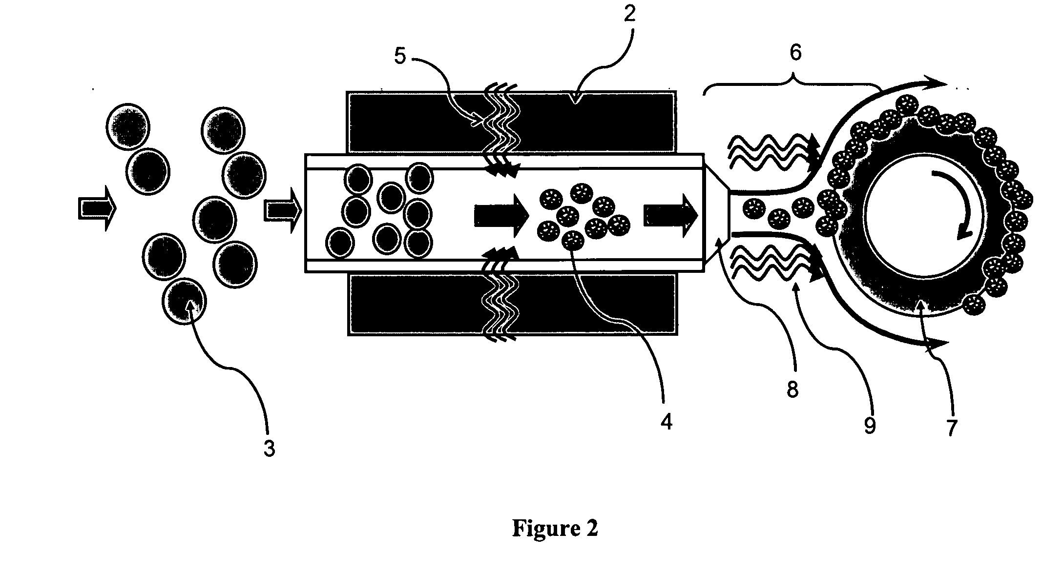
[0034]FIG. 1 shows a schematic diagram of a preferred embodiment of the invention in which a optical fiber preform substrate rod or tube is fed into an optical fiber preform reactor and subsequently coated with deposition particles, thus creating a layered perform structure having an index of refraction that can vary with radial distance from the center of the optical fiber. The perform substrate can later be further sintered and drawn, along with the coating material or removed before drawing and so act as a mandrel. In the preferred operation of this embodiment, deposition particle precursor particles are formed as an aerosol of liquid droplets by an aerosol generator (1) and carrier gas in which the aerosol particles contain an essentially optically transparent matrix material and a dopant or additive that changes a property of the material. In the preferred embodiment, the matrix material is silica, however other suitable materials are possible according to the invention. In the...


PUM

PropertyMeasurementUnit
Diameteraaaaaaaaaa
Diameteraaaaaaaaaa
Diameteraaaaaaaaaa

Abstract

The present invention relates to a method and apparatus for fiber and / or fiber perform production and in particular, optical fiber and optical fiber preform production in which a fiber substrate and a multilayered preform can be continuously produced. The layered preform is constructed from particles deposited from one or more aerosol streams containing multicomponent particles wherein individual particles have the ratio of components as desired in the perform layer. Preferably, the components of the aerosol particles have a sub-particle structure in which the subparticle structure dimensions are smaller than the particle diameter and more preferably smaller than the wavelength of light and more preferably on the molecular scale. Preferably, the particles are deposited on the perform substrate via one or more deposition units. Multiple deposition units can be operated simultaneously and / or in series. As the preform is synthesized, it can be simultaneously fed into a drawing furnace for continuous production of fiber. The method can also be used for batch production of fiber preforms and fiber.

Description

[0001] This claims the benefit of provisional application U.S. No. 60 / 762,853.1. BACKGROUND OF THE INVENTION [0002] 1. Field of the Invention [0003] The present invention relates to a method and apparatus for fiber and / or perform production and in particular optical fiber and / or optical fiber perform production in which an fiber substrate and a multilayered preform can be continuously produced. The layered preform is constructed from multicomponent particles deposited from one or more aerosol streams wherein the individual particles have the ratio of components as desired in the perform layer. Preferably, the components of the aerosol particles have a sub-particle structure in which the sub-particle structure dimensions are smaller than the particle diameter and more preferably smaller than the wavelength of light and more preferably on molecular dimensions. Preferably, the particles are deposited on the perform substrate via one or more deposition units. Multiple deposition units c...

Claims


Application Information

Patent Timeline
IPC IPC(8): C03B37/02
CPCC03B37/01294C03B2205/30C03B37/027
Inventor BROWN, DAVID PAUL
Owner BROWN DAVID P
Learn More