
Minimally invasive bone manipulation device and method of use

a bone retraction and minimally invasive technology, applied in the field of surgical instruments, can solve the problems of undesirable expansion of bone or bone fragments, unsuitable retraction of tissue in a different type of surgery, and increase the challenge of surgeons, so as to avoid undesirable contact with surrounding tissue and bone, and less invasive

Active Publication Date: 2007-10-11
ZIMMER BIOMET SPINE INC
View PDF60 Cites 62 Cited by
  • Summary
  • Abstract
  • Description
  • Claims
  • Application Information

AI Technical Summary

Benefits of technology

[0008] The present teachings provide a less invasive surgical device, which can be precisely controlled by the surgeon to expand tissue and transmit sufficient force to manipulate bone in a selected direction or, if desired, in multiple directions. Further, the present teachings provide a device that protects the mechanism from unwanted contact with surrounding tissues, where such contact might result in occlusion or fouling of the mechanism such that the function of the device is compromised. SUMMARY
[0009] The present teachings generally provide a device designed for use as a less invasive means of controllably manipulating a damaged bone, and in particular a patient's vertebra to create a void therein so as to enable a surgeon to accomplish a surgical procedure while providing a protective member on the mechanism to avoid undesirable contact with surrounding tissue and bone.

Problems solved by technology

It is, however, often the case that one tissue retractor designed for use in a particular surgical procedure will be completely unsuitable for retraction of tissue in a different type of surgery.
The close proximity of the spinal cord to damaged sections of a vertebra, which are in need of surgical repair, presents a particularly hazardous situation for the patient and increases the challenge for the surgeon tremendously.
Balloon-type expansion devices are uncontrolled and multi-directional, which can lead to undesirable expansion of the bone or bone fragments being displaced in unwanted directions
Conventionally used tissue expansion devices are each configured to precisely meet the specific needs for particular surgical procedures and, as such, are not readily (if at all) adaptable to meet the needs of a different surgical procedure.
Conventional devices share the common problem of possibly suffering mechanical interference or fouling of the mechanism when tissue or bone come into contact with the internal mechanism of the devices.
Such fouling of the mechanism by involvement with tissue or bone during the insertion process, expansion process, or the retraction process can severely limit the effectiveness of such a device.
Each possibility presents a unique problem for the surgeon using an unprotected manipulating device, such as, for example, if the mechanism becomes fouled or occluded during the insertion process, it may fail to operate once it is properly in place.
Similarly, it is possible that during operation of the expansion mechanism, the exposed mechanism can become occluded and thus limit or fully stop the expansion process.
Finally, if the unprotected mechanism is fouled or hung-up on tissue or bone during the retraction or removal process, the removal may be impeded so as to require additional surgical procedures to successfully extract the device.

Method used


Image

  • Minimally invasive bone manipulation device and method of use
  • Minimally invasive bone manipulation device and method of use
  • Minimally invasive bone manipulation device and method of use

Examples


Embodiment Construction

[0024] The following description is merely exemplary in nature and is not intended to limit the present disclosure, application, or uses.

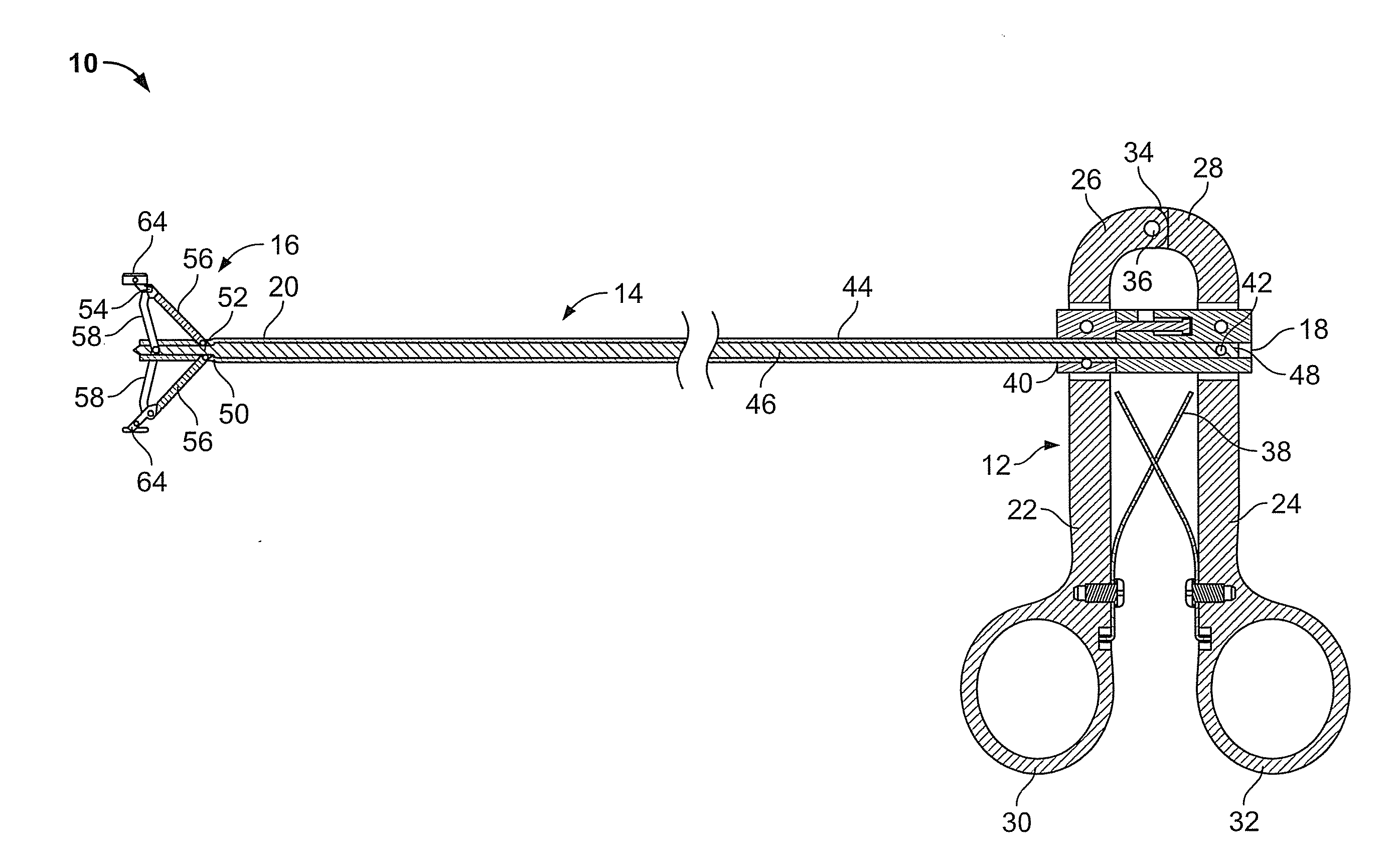
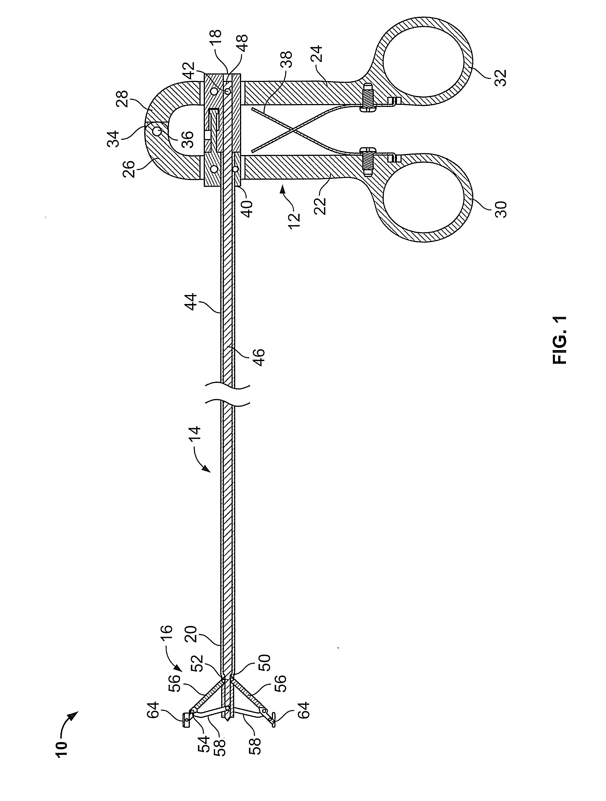
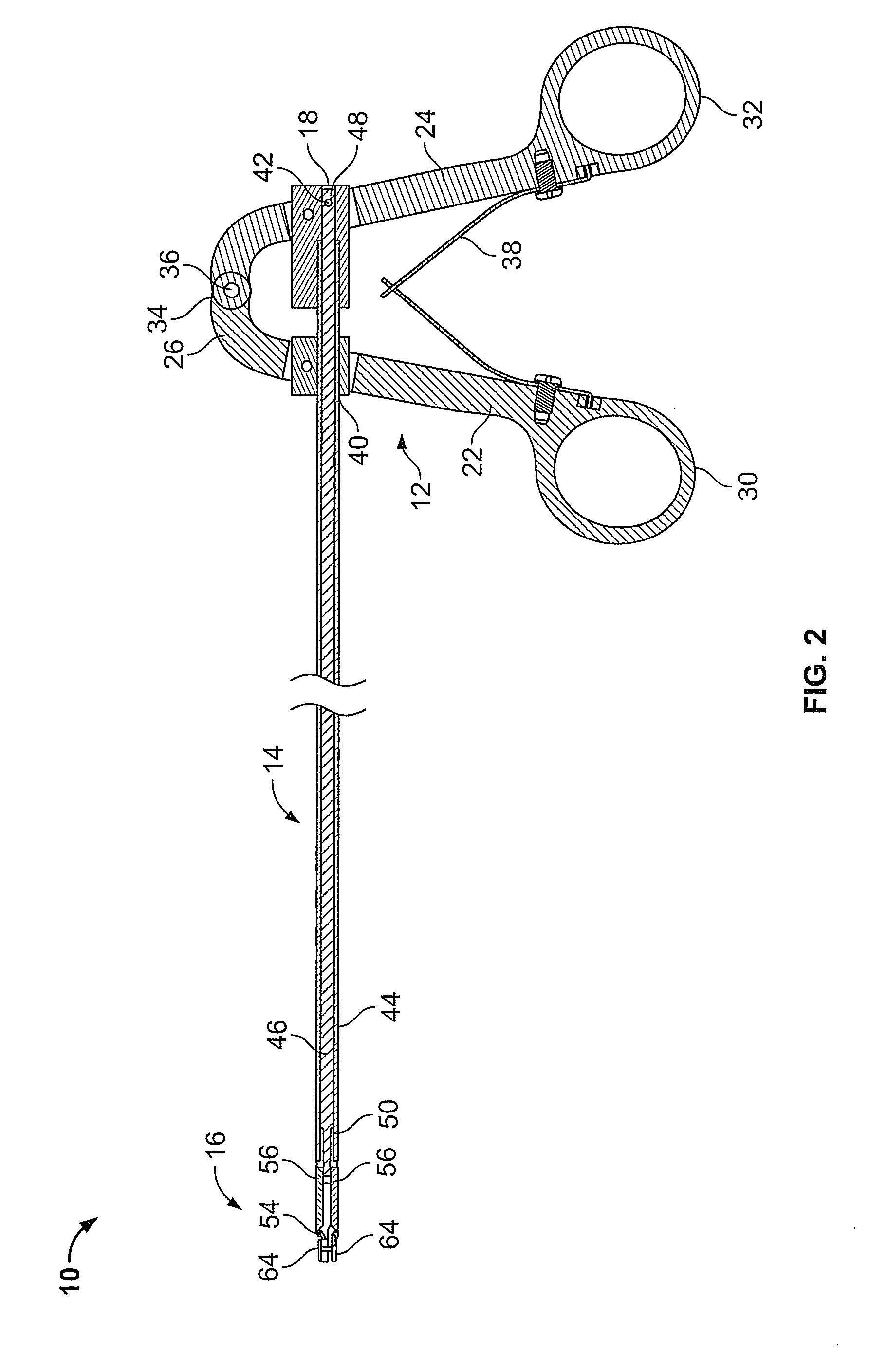
[0025] The apparatus and method of the present teachings can be adapted for use in a variety of surgical procedures which require precise tissue manipulation by a surgeon. The following description and associated FIGS. 1-11C are provided as non-limiting examples of the present teachings, which is defined with particularity only by the claims of the present teachings.

[0026] As shown in FIGS. 1-10, a tissue manipulation device (10) is provided. In one aspect, the device is configured to be particularly well-suited to the manipulation of bone in a subject. By way of example, the device (10), as best shown in FIGS. 1-9, includes three portions or assemblies which can be integrally formed or separately fabricated prior to being joined to form the device (10).

[0027] The three assemblies, which together form the device (10), include a handle assembly (...


PUM


Abstract

A surgical apparatus. The apparatus includes a handle structure, a shaft structure coupled to the handle structure, and a spreading structure coupled to the shaft structure and movable between a compact and an expanded configuration. The apparatus includes a protective sheath of shape-recovery material. The protective sheath covers the entire spreading structure in a substantially form fitting manner in any configuration of the spreading structure including the compact configuration, the expanded configuration and any configurations therebetween.

Description

CROSS-REFERENCE TO RELATED APPLICATIONS [0001] This application is a continuation of U.S. patent application Ser. No. 10 / 861,865 filed on Jun. 7, 2004, which is a continuation-in-part of U.S. application Ser. No. 10 / 389,818, filed Mar. 18, 2003 which claims priority to U.S. Provisional Application Ser. No. 60 / 365,026 filed Mar. 18, 2002. The disclosures of the above applications are incorporated herein by reference.INTRODUCTION [0002] The present teachings relate to a surgical apparatus for use in orthopedic surgery procedures. Particularly, the present teachings relate to the treatment of traumatic, pathogenic, or osteoporotic bone conditions of human and other animal body systems and, more particularly, to a novel apparatus and method for manipulating the vertebral body through a less invasive, percutaneous, surgical approach. [0003] Surgical procedures frequently require that after surgical entry has been made the tissues within the patient's body must be expanded away from the s...

Claims


Application Information

Patent Timeline
Patent Type & Authority Applications(United States)
IPC IPC(8): A61B17/58A61B17/02
CPCA61B17/00234A61B17/02A61B17/0206A61B2017/0256A61B17/025A61B17/8858A61B17/0218
Inventor BHATNAGAR, MOHITMAJOR, ERIC D.WOODS, RICHARD W.JONES, SCOTT A.CRIPE, ROBERT A.MATHUR, SANJOG KUMAR
Owner ZIMMER BIOMET SPINE INC
Learn More