Method and device for aligning an optical element

a technology of optical elements and adjusting devices, applied in the direction of optics, mountings, radiation/particle handling, etc., can solve the problems of inability to change, no longer possible, large expense, etc., and achieve the effect of improving adjustment resolution and avoiding operation

Inactive Publication Date: 2007-10-11
INCOATEC
View PDF8 Cites 7 Cited by
  • Summary
  • Abstract
  • Description
  • Claims
  • Application Information

AI Technical Summary

Benefits of technology

[0018]This solution is particularly advantageous in that the position of the point of engagement for turning may be at each location of the adjusting ring, i.e. can be freely selected about a periphery of 360°. A further property which is very important for the flexibility is that the inner optical element can also be installed at any angle between 0° and 360°.
[0020]The inventive adjusting device provides hitherto unknown flexibility in view of possible location, type and arrangement of the drive elements, the type, length and installation position of the used optical elements and the selectable adjusting direction, without having to reconstruct the adjusting device.
[0026]In one particularly preferred embodiment of the inventive device, the optical element is disposed in the holding device such that it floats. For adjusting simple mirrors, floating disposal of the holding device on one axis is sufficient. However, for mirrors having two mirror surfaces (double mirrors), a cardanic, two-axes floating support is preferred. This prevents the holding device or the optical element fixed therein from moving in other directions than desired.
[0036]The adjusting rings are advantageously operated using a gear or transmission reduction, which increases the adjustment resolution.

Problems solved by technology

Moreover, compared to conventional adjusting devices, the adjusting elements of the inventive adjusting device require very little space.
This is not possible with conventional adjusting devices, since there are functional specifications for the type of adjusting components of conventional adjusting devices depending on the type of system.
In most cases, a change is no longer possible or would require great expense.

Method used


Image

  • Method and device for aligning an optical element
  • Method and device for aligning an optical element
  • Method and device for aligning an optical element

Examples


Embodiment Construction

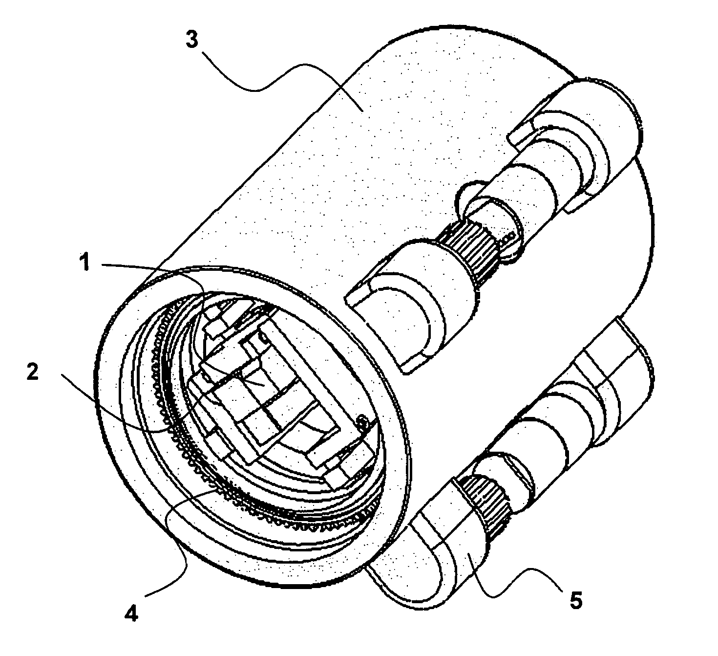
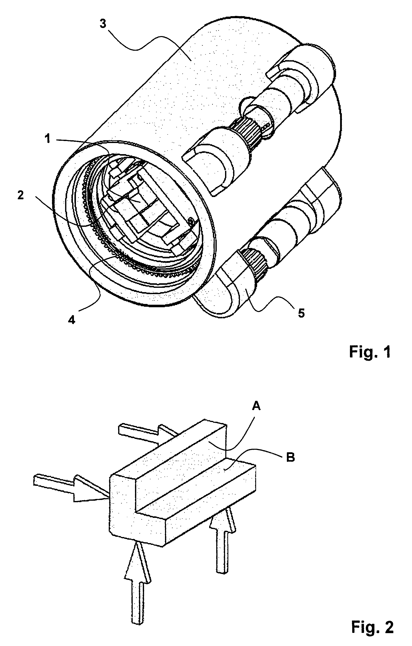
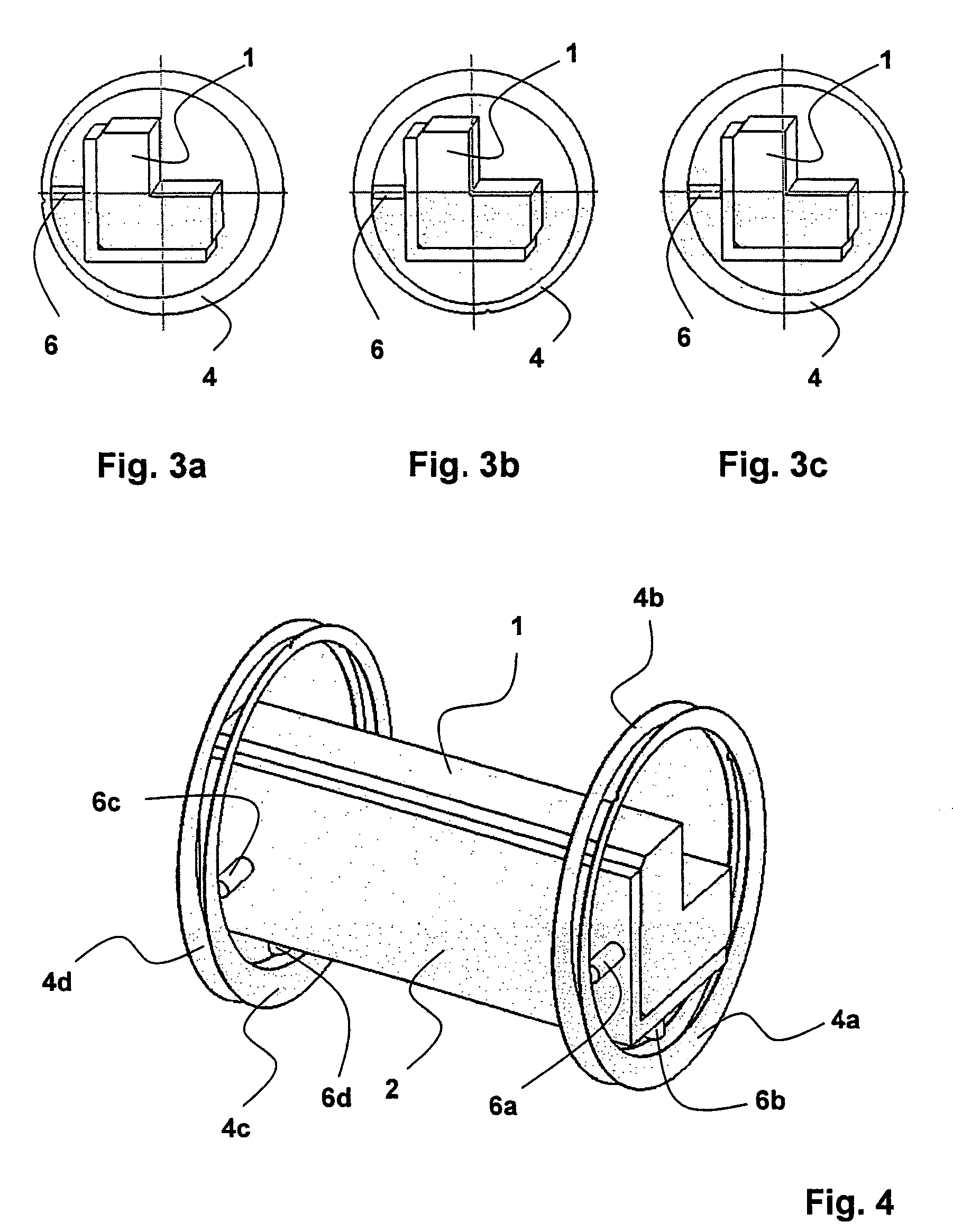
[0048]FIG. 1 shows an inventive adjusting device for adjusting optical elements. The optical element, in the present case a mirror 1, is fixed in a holding device 2 which is disposed within a housing 3. The mirror may be fixed e.g. magnetically. The inventive adjusting device comprises adjusting units which each comprise one rotatably disposed adjusting ring 4 with an eccentric recess, and one adjusting element 5.

[0049]The inventive adjusting device is preferably used for adjusting X-ray mirrors. There are two different types of X-ray mirrors: mirrors with a reflection surface and mirror combinations with two reflection surfaces. The reflection surfaces itself may have the most differing surface shapes, depending on the function. The surface may be one-dimensionally concave, convex or planar or follow a complex mathematical function, e.g. a parabolic or elliptical function. It may also be deformed in the second dimension, such that the reflecting surface corresponds e.g. to a parabo...


PUM


Abstract

A device for adjusting optical elements, in particular, for X-ray analysis, comprising a holding device (2) for receiving the optical element and at least two adjusting units at least one of the two longitudinal ends of the holding device (2), wherein the adjusting units each comprise one plunger (6, 6a, 6b, 6c, 6d), characterized in that each adjusting unit comprises a rotatably disposed adjusting ring (4, 4a, 4b, 4c, 4d) with an eccentric recess, and the optical element is mechanically coupled to the inner surfaces (7) of the adjusting rings (4, 4a, 4b, 4c, 4d) via the plungers (6, 6a, 6b, 6c, 6d). The adjusting device is compact, can be flexibly used and provides simple adjustment of the optical element.

Description

[0001]This application claims Paris Convention priority of DE 10 2006 015 933.0 filed Apr. 5, 2006 the complete disclosure of which is hereby incorporated by reference.BACKGROUND OF THE INVENTION[0002]The invention concerns a device for adjusting optical elements, in particular, for X-ray analysis, comprising a holding device for receiving the optical element, and at least two adjusting units, wherein each adjusting unit comprises one plunger. The invention also concerns a method for adjusting an optical element.[0003]A device of this type is disclosed e.g. in the manual “Confocal Max-Flux Optics™” of the company Osmic Inc.[0004]Optical elements, in particular X-ray mirrors, are used in X-ray analysis for monochromatisation, alignment or bundling of X-rays along the path from the X-ray source to the sample and from the sample to the detector.[0005]Multi-layer X-ray mirrors have been used in the optical radiation path for some years in laboratory X-ray analysis devices such as e.g. X...

Claims


Application Information

Patent Timeline
IPC IPC(8): G02B7/02
CPCG21K2201/06G02B7/1824
Inventor WINGS, GERDHOFFMANN, CHRISTIANWULF, KLAUSMICHAELSEN, CARSTEN
Owner INCOATEC
Why Eureka
Try Eureka