
Molded body cutting apparatus, method for cutting ceramic molded body and method manufacturing honeycomb structured body

a technology of molded body and cutting apparatus, which is applied in the manufacture of cheese, conveyor parts, bread, etc., can solve the problems of affecting the health of the environment and the human body caused by particulates such as soot in exhaust gas discharged from the internal combustion engines of buses, trucks and other vehicles, construction equipment and the lik

Inactive Publication Date: 2007-10-11
IBIDEN CO LTD
View PDF97 Cites 102 Cited by
  • Summary
  • Abstract
  • Description
  • Claims
  • Application Information

AI Technical Summary

Benefits of technology

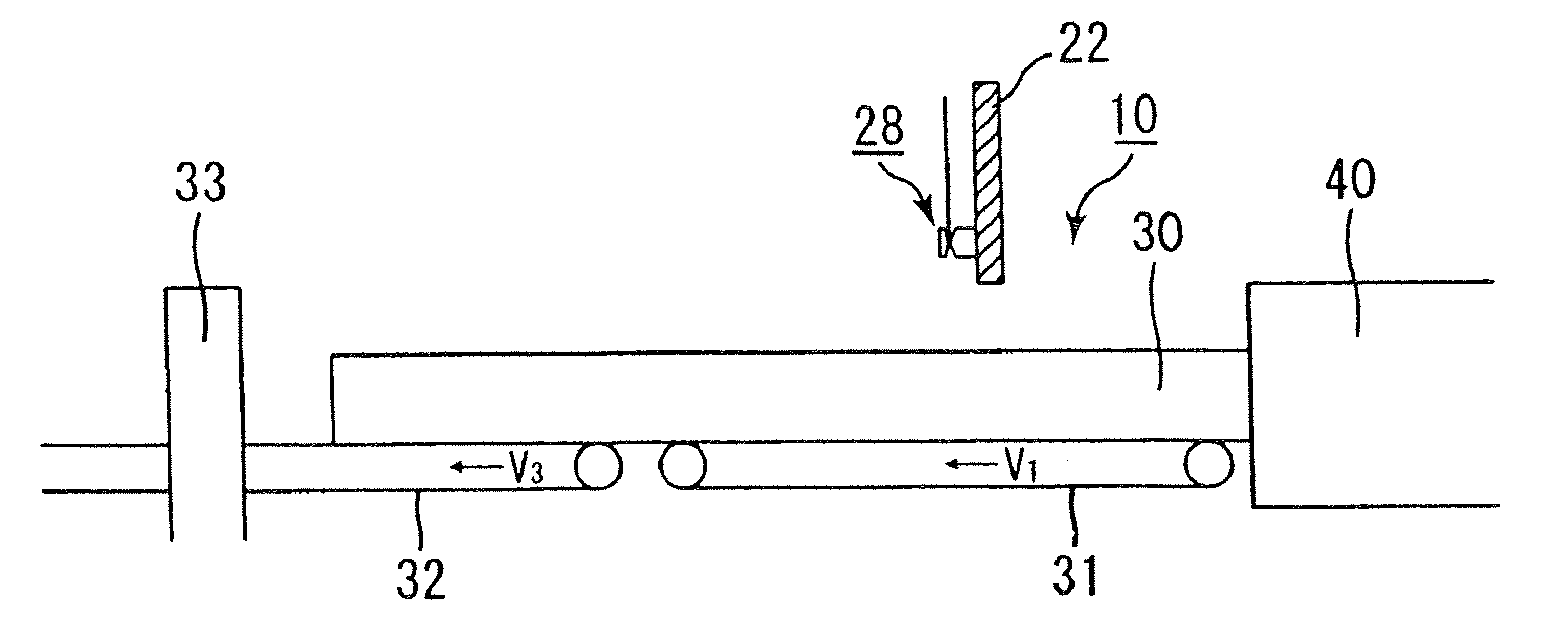
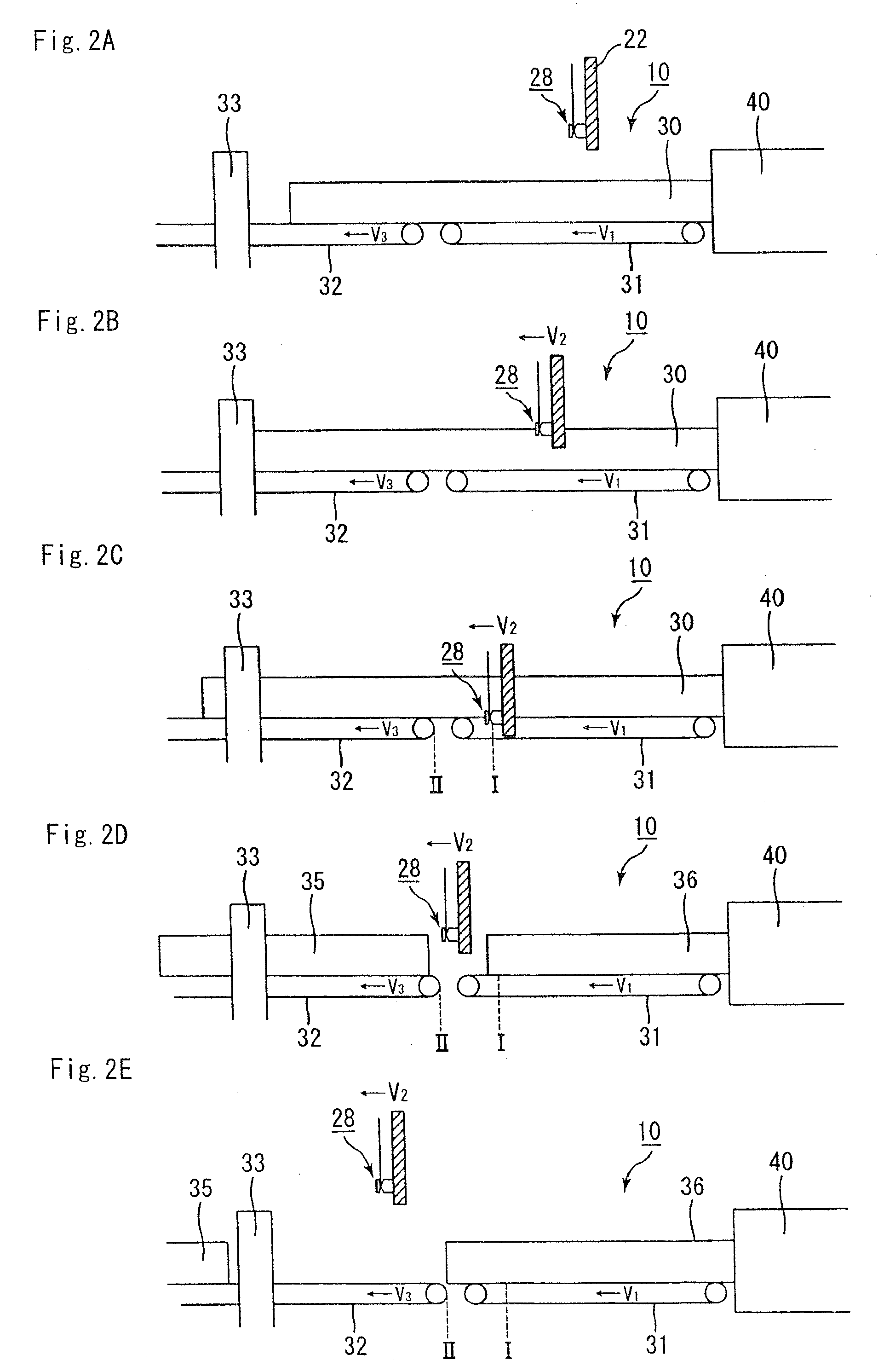
[0018]each of the conveyance speed of the first conveyer member, the movement speed of the cutting member in the parallel direction, and a conveyance speed of the second conveyer member becomes faster toward the latter, after the ceramic molded body is cut.

Problems solved by technology

Harm to the environment and the human body caused by particulates such as soot contained in exhaust gas discharged from the internal combustion engines of buses, trucks and other vehicles, construction equipment and the like has recently become a problem.

Method used


Image

  • Molded body cutting apparatus, method for cutting ceramic molded body and method manufacturing honeycomb structured body
  • Molded body cutting apparatus, method for cutting ceramic molded body and method manufacturing honeycomb structured body
  • Molded body cutting apparatus, method for cutting ceramic molded body and method manufacturing honeycomb structured body

Examples


example 1

[0279]250 kg of α-type silicon carbide powder having a mean particle diameter of 10 μm, 100 kg of α-type silicon carbide powder having a mean particle diameter of 0.5 μm, and 20 kg of organic binder (methyl cellulose) were blended together to prepare a powder mixture.

[0280]Next, 12 kg of lubricating agent (UNILUBE, Manufactured byNOFCorp.), 5 kg of plasticizer (glycerin), and 65 kg of water were blended in a separate container to prepare a liquid mixture. Next, using a wet mixing machine, the powder mixture and the liquid mixture were blended together, thereby preparing the wet mixture.

[0281]And the moisture content of the above prepared wet mixture was 14% by weight.

[0282]Next, using a conveyer apparatus, the wet mixture was conveyed to the extrusion-molding machine, and put into the raw material induction port of the extrusion-molding machine.

[0283]The moisture content of the wet mixture immediately before being put into the extrusion-molding machine was 13.5% by weight. The wet m...

examples 2 , 3

Examples 2, 3

[0287]Except the point of setting the diameter of the filamentous body cutting member to the value indicated in Table 1-1, the honeycomb molded body was produced by cutting the honeycomb molded body in the same manner as of the Example 1.

examples 4 , 5

Examples 4, 5

[0288]Except the point of setting the conveyance speed of the first conveyer member, the movement speed of the cutting member in the parallel direction, and the conveyance speed of the second conveyer member after cutting the honeycomb molded body to the values indicated in Table 1-1, the honeycomb molded body was produced by cutting the honeycomb molded body in the same manner as of the Example 1.


PUM

PropertyMeasurementUnit
diameteraaaaaaaaaa
diameteraaaaaaaaaa
lowering speedaaaaaaaaaa

Abstract

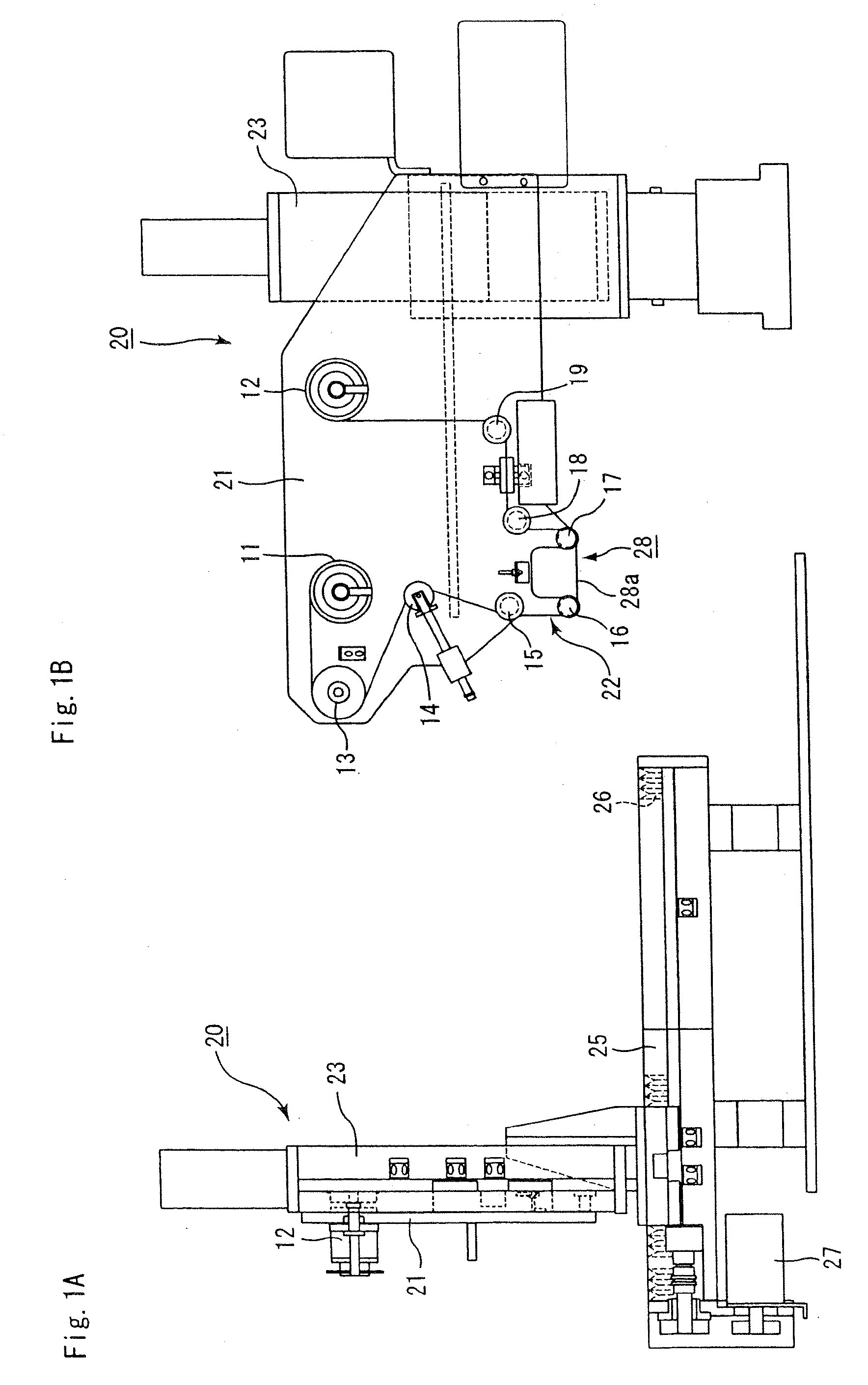
A molded body cutting apparatus according to the present invention comprising a first conveyer member that conveys an extrusion-molded pillar-shaped ceramic molded body a cutting member that moves in a direction parallel to a movement direction of the above mentioned first conveyer member while moving also in a vertical direction, and cuts the above mentioned ceramic molded body to a predetermined length by passing through the interior of the above mentioned ceramic molded body and a second conveyer member that conveys a cut ceramic molded body cut to a predetermined length by the above mentioned cutting member, wherein a conveyance speed of the above mentioned first conveyer member and a movement speed of the above mentioned cutting member in the above mentioned parallel direction are almost the same, before the above mentioned ceramic molded body is cut, and each of the conveyance speed of the above mentioned first conveyer member, the movement speed of the above mentioned cutting member in the above mentioned parallel direction, and a conveyance speed of the above mentioned second conveyer member becomes faster toward the latter, after the above mentioned ceramic molded body is cut.

Description

CROSS-REFERENCE TO RELATED APPLICATIONS[0001]This application claims priority of PCT / JP2006 / 307645 filed on Apr. 11, 2006. The contents of this application are incorporated herein by reference in their entirety.BACKGROUND OF THE INVENTION[0002]1. Field of the Invention[0003]The present invention relates to a molded body cutting apparatus, a method for cutting a ceramic molded body, and a method for manufacturing a honeycomb structured body.[0004]2. Discussion of the Background[0005]Harm to the environment and the human body caused by particulates such as soot contained in exhaust gas discharged from the internal combustion engines of buses, trucks and other vehicles, construction equipment and the like has recently become a problem.[0006]To remedy this, there has been currently proposed numerous kinds of ceramic filters using a honeycomb structured body made of porous ceramic as a filter for capturing particulates contained in exhaust gas, thereby purifying the exhaust gas.[0007]Con...

Claims


Application Information

Patent Timeline
Patent Type & Authority Applications(United States)
IPC IPC(8): B29C47/12B26D3/00B29C47/00B23D25/02C04B33/32B28B1/00B29C48/30
CPCB26D1/547B26D1/60C04B2111/0081C04B2111/00793C04B2111/00129C04B38/0006C04B35/565B28B11/166B28B11/163C04B38/0054C04B38/0074C04B38/067C04B38/068C04B38/085Y10T83/465Y10T83/0462Y10T83/05
Inventor YAMAMURA, NORIHIKONARUSE, KAZUYASUMIYA, EIJI
Owner IBIDEN CO LTD
Learn More